
Overwater high-speed carrying vehicle
A vehicle, high-speed technology, applied in the direction of transportation and packaging, ships, hydrodynamic characteristics/hydrostatic characteristics, etc., can solve the problem of not being able to greatly increase the speed, and achieve increased speed, reduced water resistance, and increased speed. Effect
Patent Information
- Authority / Receiving Office
- CN · China
- Patent Type
- Applications(China)
- Current Assignee / Owner
- Publication Date
- 2017-09-15
Smart Images
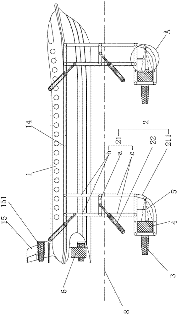
Figure 1 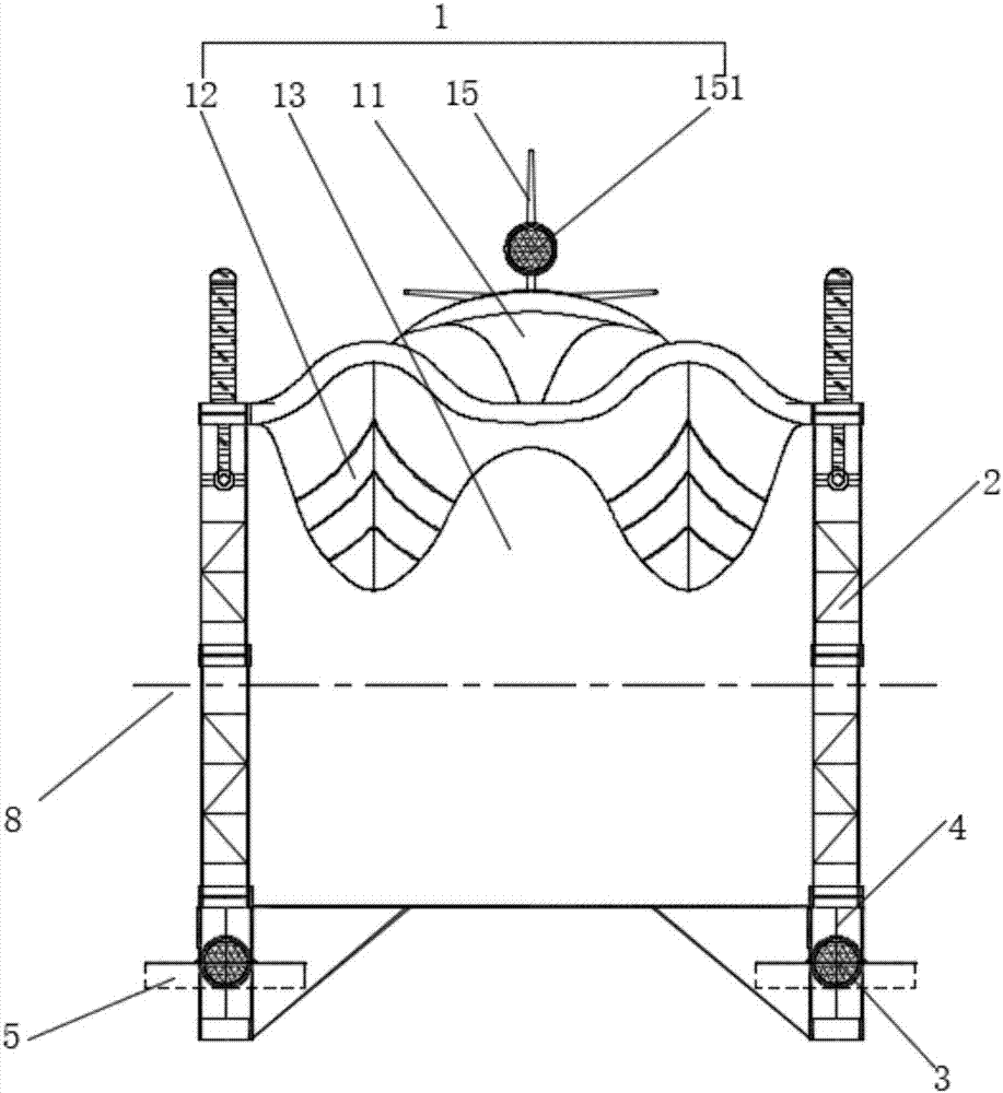
Figure 2 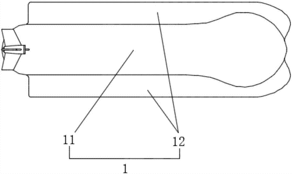
Figure 3
Abstract
Description
technical field
[0001] The invention belongs to the field of water transportation, in particular to a high-speed water vehicle. Background technique
[0002] "Supercavitation ship" is to make the entire hull surface of the ship covered by air bubbles, so that the hull is not directly in contact with water, reducing water resistance and increasing speed.
[0003] The "supercavitation ship" is a high-speed vehicle on water, also known as a hydrofoil speedboat. The bottom of the hydrofoil speedboat is equipped with hydrofoils, which rely on the hydrodynamic force generated by the hydrofoils to support the weight of the hull and make the hull leave the water to reduce water resistance and increase speed. However, the hydrofoil of the hydrofoil speedboat is still submerged in the water, and is also subject to water frictional resistance, so the speed of the ship cannot be greatly improved. The envisioned supercavitation hydrofoil speedboat is to make the hydrofoil at the bottom...
Examples
Embodiment 1
[0039] Embodiment 1: a kind of high-speed vehicle on water, such as figure 1 As shown, it includes a hull 1, a hull water level regulating system 2 and an underwater thrust system 3.
[0040] combine figure 2 and image 3As shown, the hull 1 includes a cabin 11 and two floating bodies 12 arranged on both sides of the bottom of the cabin 11. A notch 13 is formed between the two floating bodies 12, and the surfaces of the floating body 12 and the notch 13 are arranged in a streamlined shape.
[0041] The hull water level regulating system 2 includes four lifting frames 21, which are pushed and pulled by piston cylinders 22 to expand and contract. Four lifting frames 21 are evenly arranged on both sides of the hull 1 . The price increase rack 21 includes a main rod a, two first hinged rods b and two second hinged rods c; The two ends are hinged; one end of two second hinged rods c arranged in parallel is hinged with the underwater main frame 211 respectively, and the other e...
Embodiment 2
[0049] Embodiment 2: a kind of high-speed vehicle on water, such as Figure 6 and Figure 7 As shown, the difference from Embodiment 1 is that there are two lifting frames 21, which are distributed in the notch 13 below the central axis of the hull 1 one after the other, and the two lifting frames 21 are jointly connected with an underwater main frame 211 Fixed connection, each lifting frame 21 is provided with a piston cylinder 22, the cylinder body of the piston cylinder 22 is hinged with the mounting frame 14, and its piston rod is hinged with any hinge rod b, and the first hinge rod b of the two lift frames 21 The direction of rotation is reversed by being pushed and pulled by the piston cylinder 22, so that the underwater main body frame 211 rises and falls up and down.
[0050] And the bearing balance plate 51 installed on the underwater body frame 211 includes a main adjustment plate 511 and a secondary adjustment plate 512 , the main adjustment plate 511 is located in...
Embodiment 3
[0053] Embodiment 3: with a kind of high-speed vehicle on water, such as Figure 11 and Figure 12 As shown, the difference from Embodiment 2 is that, besides the above-mentioned hydraulic cylinder transmission mode, the driving lifting frame 21 and the bearing balance plate 51 can also adopt the screw transmission mode, and the specific structure is as follows.
[0054] Each lifting frame 21 is provided with a telescopic cylinder 23, and the telescopic cylinder 23 includes a screw rod 231 driven by a motor, and a fixed sleeve 232 and a connecting sleeve 233 respectively installed on the two ends of the screw rod 231. The fixed sleeve 232 is sleeved outside one end of the screw rod 231 and It is threadedly connected with the screw rod 231 , and the connecting sleeve 233 is sleeved on the other end of the screw rod 231 and is rotatably connected with the screw rod 231 and fixed in the axial direction. The fixed sleeve 232 is hinged with the mounting bracket 14, and the connect...