
Combined installation rack for windowsill lamp
A technology of mounting frame and window sill, applied in the field of window sill lamp combination mounting frame, can solve the problems of increased heat, large heat generation, inconvenient operation, etc., and achieves the effect of satisfying guests' meals, low manufacturing cost, and good heat dissipation effect.
Patent Information
- Authority / Receiving Office
- CN · China
- Patent Type
- Applications(China)
- Current Assignee / Owner
- Publication Date
- 2018-02-23
- Estimated Expiration
- Not applicable · inactive patent
Smart Images
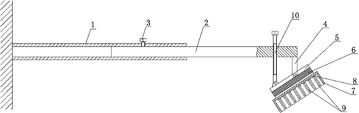
Figure 1
Abstract
Description
technical field
[0001] The invention relates to the technical field of window sill lamp structures, in particular to a combined installation frame for window sill lamps. Background technique
[0002] The window sill lamp is a light bulb installed under the eaves, which can provide convenience for pedestrians. At the same time, it can also provide people with a place to eat on summer nights, that is, multiple dining tables can be placed under the window sill lamp, and people can eat around the table. Provide a light source so that diners can pick up dishes. Yet, when the guest asked to dine outdoors, because the window sill lamp was fixedly installed and could not be moved, further guest requirements could not be met.
[0003] In order to solve this problem, some mobile bulbs are used to meet the requirements, that is, the bulbs are installed on the bracket, and the bracket can be fixed on the table legs. Although the problem can be solved temporarily, when the meal is over,...
Examples
Embodiment Construction
[0011] The present invention will be further described below in conjunction with accompanying drawing, protection scope of the present invention is not limited to the following:
[0012] Such as figure 1 As shown, a combination mounting frame for a window sill lamp, which includes a cylinder body 1 and a telescopic rod 2, one end of the cylinder body 1 is fixed on the wall, and the other end of the cylinder body 1 is inserted with a The telescopic rod 2 that the axis moves, the cylindrical surface of the cylinder body 1 is provided with a through hole, and the internal thread of the through hole is connected with a locking screw 3, and the sharp part of the locking screw 3 is pressed against the telescopic rod 2, and the telescopic rod 2 The other end of the other end is provided with through hole and bracket 4 in turn from left to right, and bracket 4 is positioned at the below of telescopic rod 2, and mounting plate 5 is hinged on support 4 through pin shaft, and the bottom ...