
Alternating current noise-eliminating negative ion generator
A negative ion generator and AC noise technology, applied in the field of air purification, can solve problems such as low sensitivity and inability to improve air, and achieve the effect of eliminating residual AC noise signals and avoiding misoperation
Patent Information
- Authority / Receiving Office
- CN · China
- Patent Type
- Applications(China)
- Current Assignee / Owner
- Publication Date
- 2018-02-23
- Estimated Expiration
- Not applicable · inactive patent
Smart Images
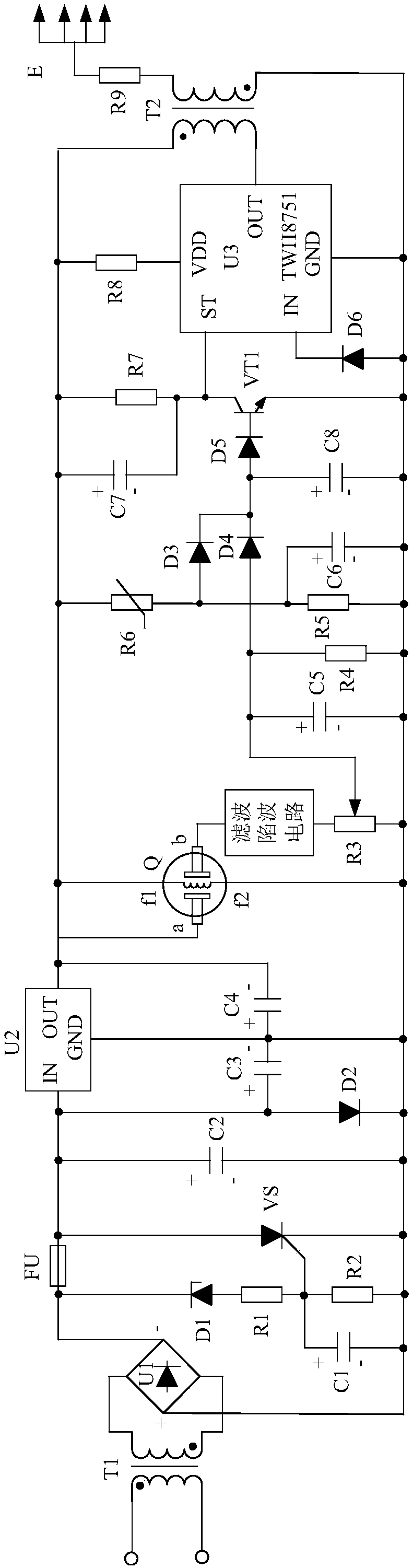
Figure 1 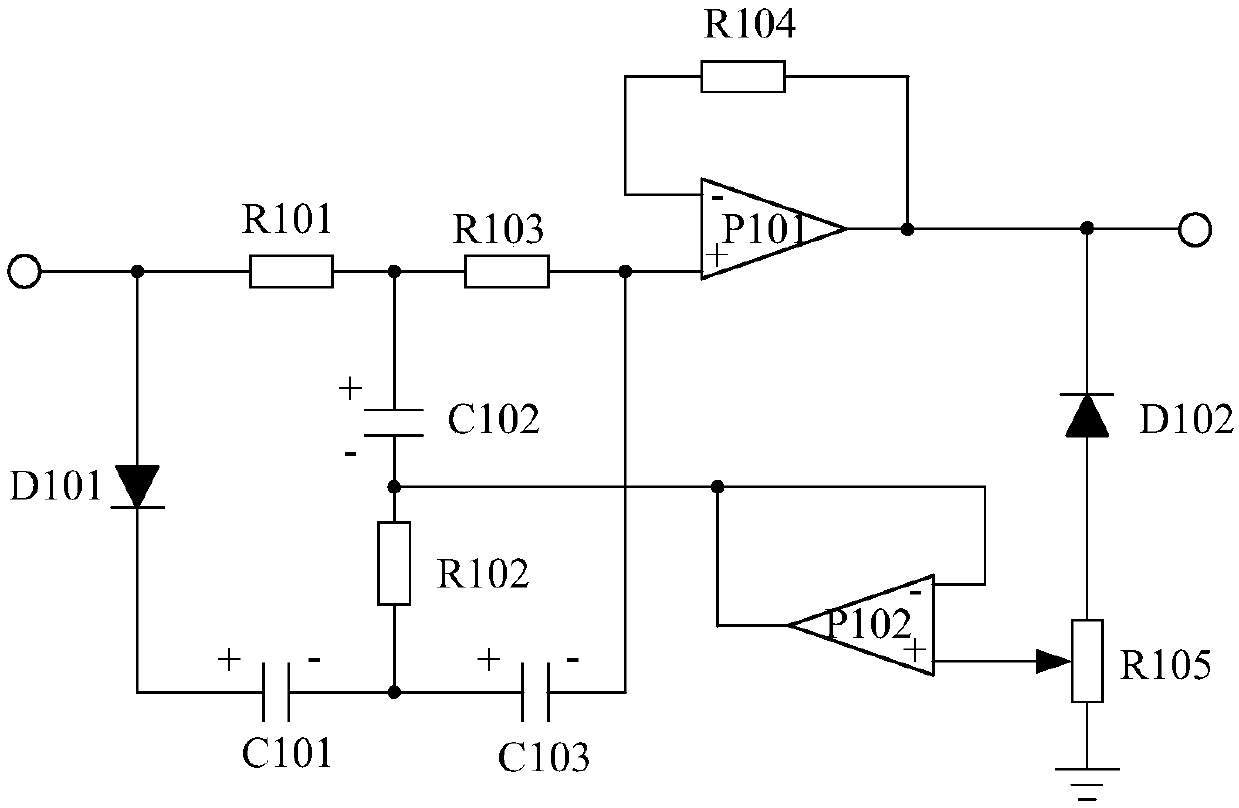
Figure 2
Abstract
Description
technical field
[0001] The invention relates to the field of air purification, in particular to an AC noise eliminating negative ion generator. Background technique
[0002] In recent years, the widespread use of air conditioners and computers and the prevalence of building decoration have led to the deterioration of indoor air quality. Toxic and harmful gases and suspended solids exceed the standard, but healthy negative ions are seriously lacking, resulting in an increase in the incidence of diseases and a decrease in work efficiency. In order to improve air quality, various air purification technologies and equipment have emerged, including negative ion generators. The negative ion generator detects the concentration of harmful gases in the indoor air, and when the concentration of harmful gases is too high, it will automatically start to generate negative ions, so as to achieve the purpose of fresh air. Yet the sensitivity of present negative ion generator is not high,...
Examples
Embodiment
[0016] Such as figure 1 As shown, the present invention mainly consists of control chip U3, triode VT1, gas sensor Q, transformer T2, discharge terminal E, potentiometer R3, resistor R4, resistor R5, thermistor R6, resistor R7, resistor R8, resistor R9, Capacitor C5, capacitor C6, capacitor C7, capacitor C8, diode D3, diode D4, diode D5, diode D6, filter trap circuit and power supply circuit.
[0017] When connected, the potentiometer R3 is connected in series between the filter trap circuit and the f2 end of the gas sensor Q. The P pole of the diode D4 is connected with the control terminal of the potentiometer R1, and the N is connected with the base of the triode VT1 after passing through the diode D5. The positive pole of the capacitor C5 is connected to the P pole of the diode D4, and the negative pole is connected to the f2 terminal of the gas sensor Q. Resistor R4 is connected in parallel with capacitor C5. The positive pole of the capacitor C6 is connected to the f1...