
Manpower carrying trolley for round steel
A technology for handling trolleys and manpower, which is applied in trolleys, motor vehicles, single-axis trolleys, etc. It can solve the problems of small magnetic contact area on cylindrical surfaces, unsafe use, and insufficient magnetic attraction, and achieve fast transportation, labor-saving handling, and simple structure Effect
Patent Information
- Authority / Receiving Office
- CN · China
- Patent Type
- Applications(China)
- Current Assignee / Owner
- Publication Date
- 2018-03-13
Smart Images
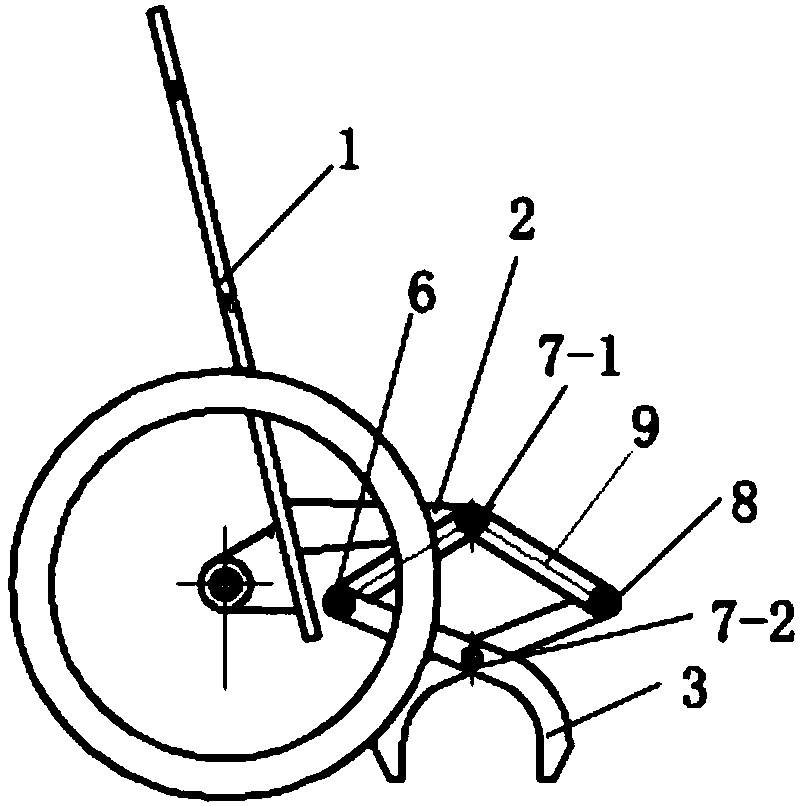
Figure 1 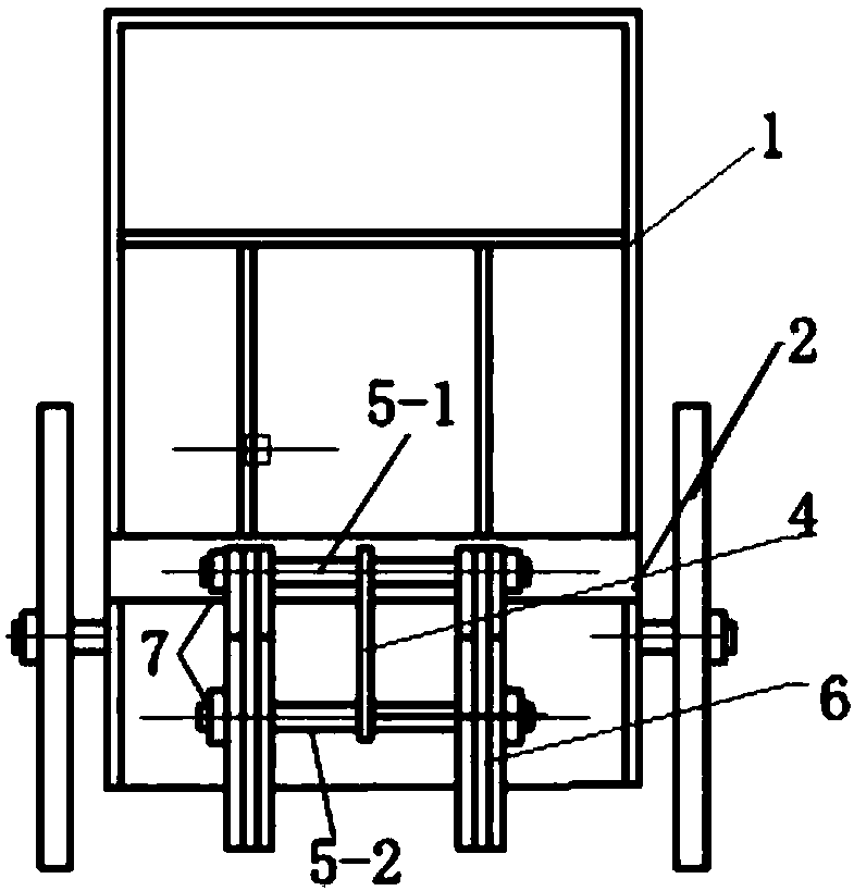
Figure 2
Abstract
Description
technical field
[0001] The invention relates to a handling tool, in particular to a round steel manual handling trolley. Background technique
[0002] Mechanized equipment, such as forklifts and cranes, can be used to transport steel materials, but the purchase cost of these equipment is relatively high, and the amount of practical consumables is not very large, let alone transported every day, and the utilization rate of equipment is not high. Therefore, many schools do not use automation or large equipment for handling. In manual handling, there are machines and equipment that use strong magnetic adsorption and handling, while magnetic handling equipment is not safe to use because of the small magnetic contact area of the cylindrical surface and insufficient magnetic attraction; the use of vehicle equipment is too large for handling, and often requires manual handling. The equipment can only be transported up. Then, if you do not use mechanized equipment, it is purely ...
Examples
Embodiment Construction
[0016] The present invention will be further explained below in conjunction with the accompanying drawings.
[0017] The invention discloses a round steel manpower handling trolley, which comprises a trolley 1 and a self-locking gripper 2 arranged on the head of the trolley 1; the self-locking gripper 2 is provided with a self-locking small hook The hand 2 includes two horizontal shafts 5 arranged in parallel up and down, and a telescopic device 6 is respectively provided at both ends of the horizontal shaft 5, and the self-locking small hook 4 is fixed on the middle section of the upper horizontal shaft 5-1; the telescopic device 6 includes two fixed Shaft 7, two movable shafts 8, and two fixed shafts 7 are arranged at the ports of the horizontal shaft 5, the fixed shaft 7 and the movable shaft 8 are connected by a connecting rod 9, and the connection between the movable shaft 8 and the lower fixed shaft 7-2 Bar 9 stretches out lower fixed shaft 7-2, and stretching out sectio...