
Structure improving low frequency sound absorption performance through magnetism
A low-frequency, sound-absorbing technology, applied in the direction of sound-producing equipment, instruments, etc., can solve the problems of reducing the damping coefficient, reducing the elastic coefficient of mechanical impedance, etc., to achieve the effect of reducing the elastic coefficient, improving the low-frequency sound absorption performance, and good viscous damping performance.
Patent Information
- Authority / Receiving Office
- CN · China
- Patent Type
- Applications(China)
- Current Assignee / Owner
- Publication Date
- 2018-08-24
Smart Images
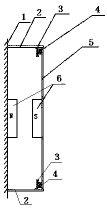
Figure 1 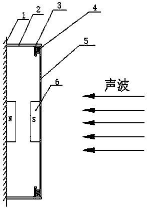
Figure 2 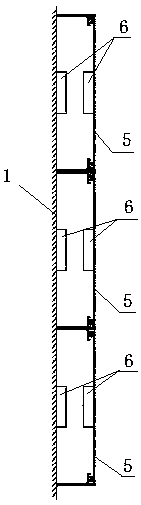
Figure 3
Abstract
Description
Technical field
[0001] The invention belongs to the field of noise control, and particularly relates to a structure with sound absorption performance, which can absorb low-frequency noise below 500 Hz. Background technique
[0002] Commonly used sound-absorbing materials for noise control structures are: glass wool, slag wool, rock wool, foam plastic, asbestos wool, felt, soft fiberboard and other porous sound-absorbing materials. Generally, porous sound-absorbing materials have good medium and high frequency absorption. Acoustic performance, but poor low-frequency sound absorption performance. The sound absorption structure of the micro-perforated plate is also often used for noise control. Its sound absorption mechanism is cavity resonance, which also has the problem of poor low-frequency sound absorption performance. In order to improve the low-frequency sound absorption, a method of thickening the sound-absorbing material layer is required. For the micro-perforated plate str...
Examples
Embodiment Construction
[0018] See figure 1 , Two transverse brackets 2 perpendicular to the wall 1 are fixedly installed on the wall 1. The two brackets 2 have the same structure and are parallel to each other. A mechanical impedance board 5 parallel to the wall 1 is arranged between the two transverse supports 2, and the mechanical impedance board 5 is parallel to the wall 1 with a certain distance therebetween. A square resonant cavity is enclosed between a mechanical impedance plate 5, two lateral supports 2 and the wall 1. A pair of magnetic material blocks 6 are arranged inside the square resonant cavity, and one of the magnetic material blocks 6 is a magnetic material. The block is fixedly connected to the wall 1, and the other one of the pair of magnetic material blocks 6 is fixedly connected to the mechanical impedance board 5. That is, a pair of magnetic material blocks 6 are located between the wall 1 and the mechanical impedance plate 5. The two magnetic material blocks of the pair of magn...