
Precise automatic revolving riveting machine
A riveting machine and automatic technology, applied in the field of precision automatic riveting machines, can solve the problems of low degree of automation, lack of lighting and magnifying observation structure, inconvenient waste collection, etc., to improve labor efficiency, improve automation, and improve work efficiency. Effect
Patent Information
- Authority / Receiving Office
- CN · China
- Patent Type
- Applications(China)
- Current Assignee / Owner
- Publication Date
- 2018-10-12
- Estimated Expiration
- Not applicable · inactive patent
Smart Images
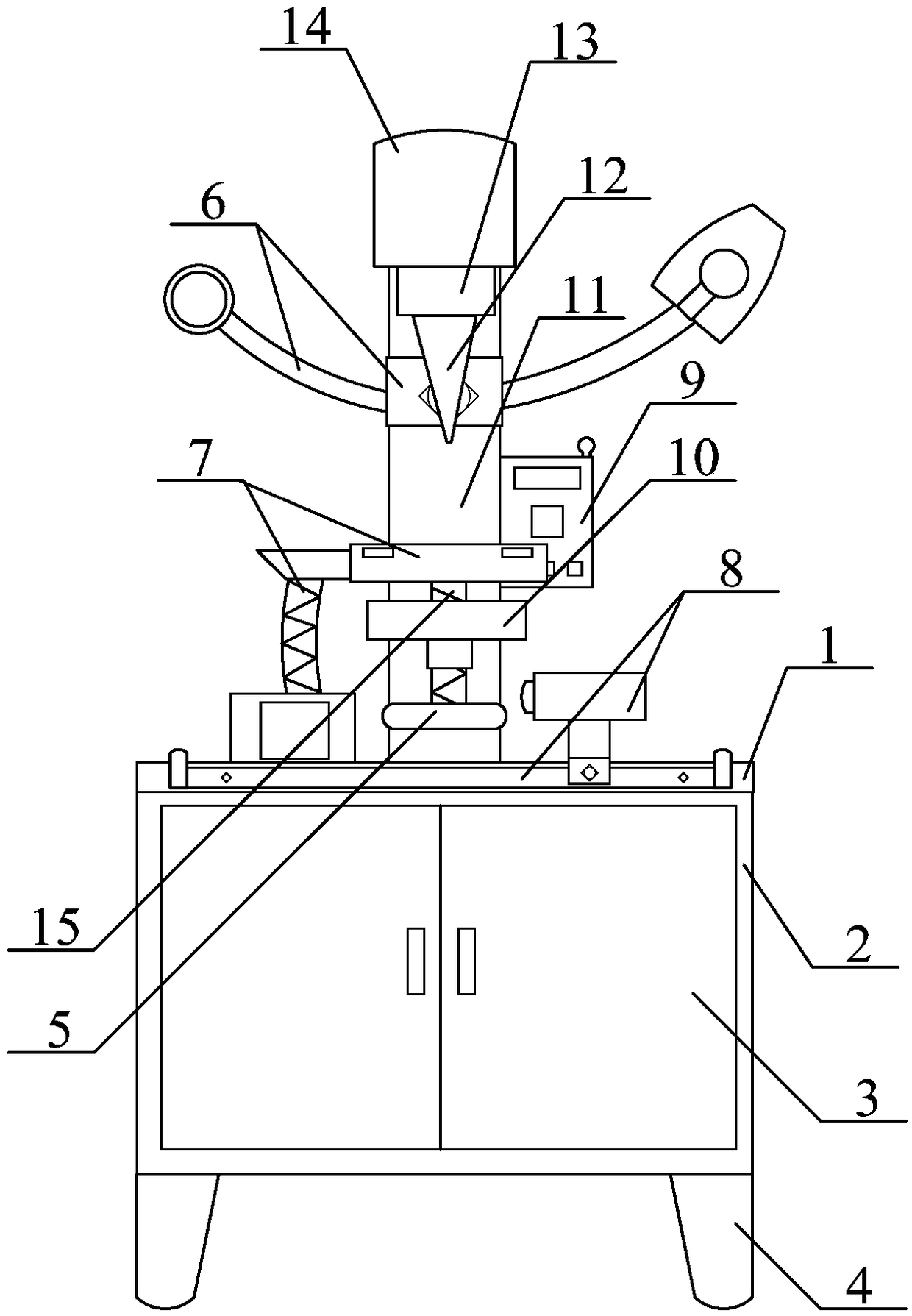
Figure 1 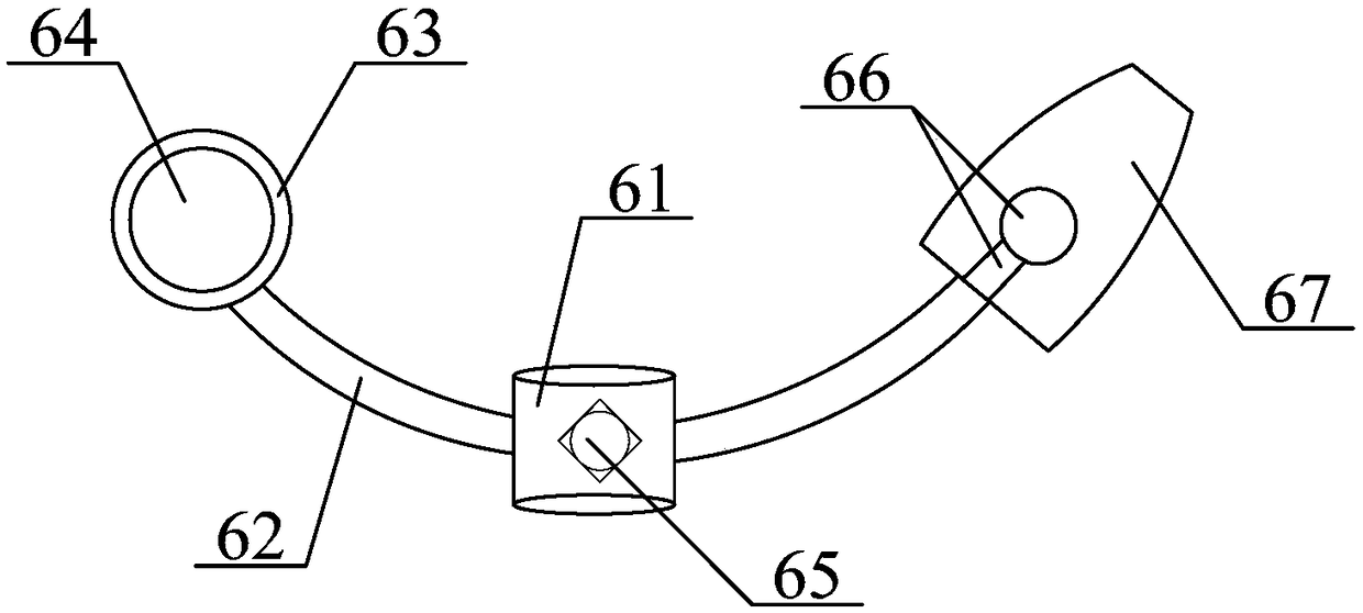
Figure 2 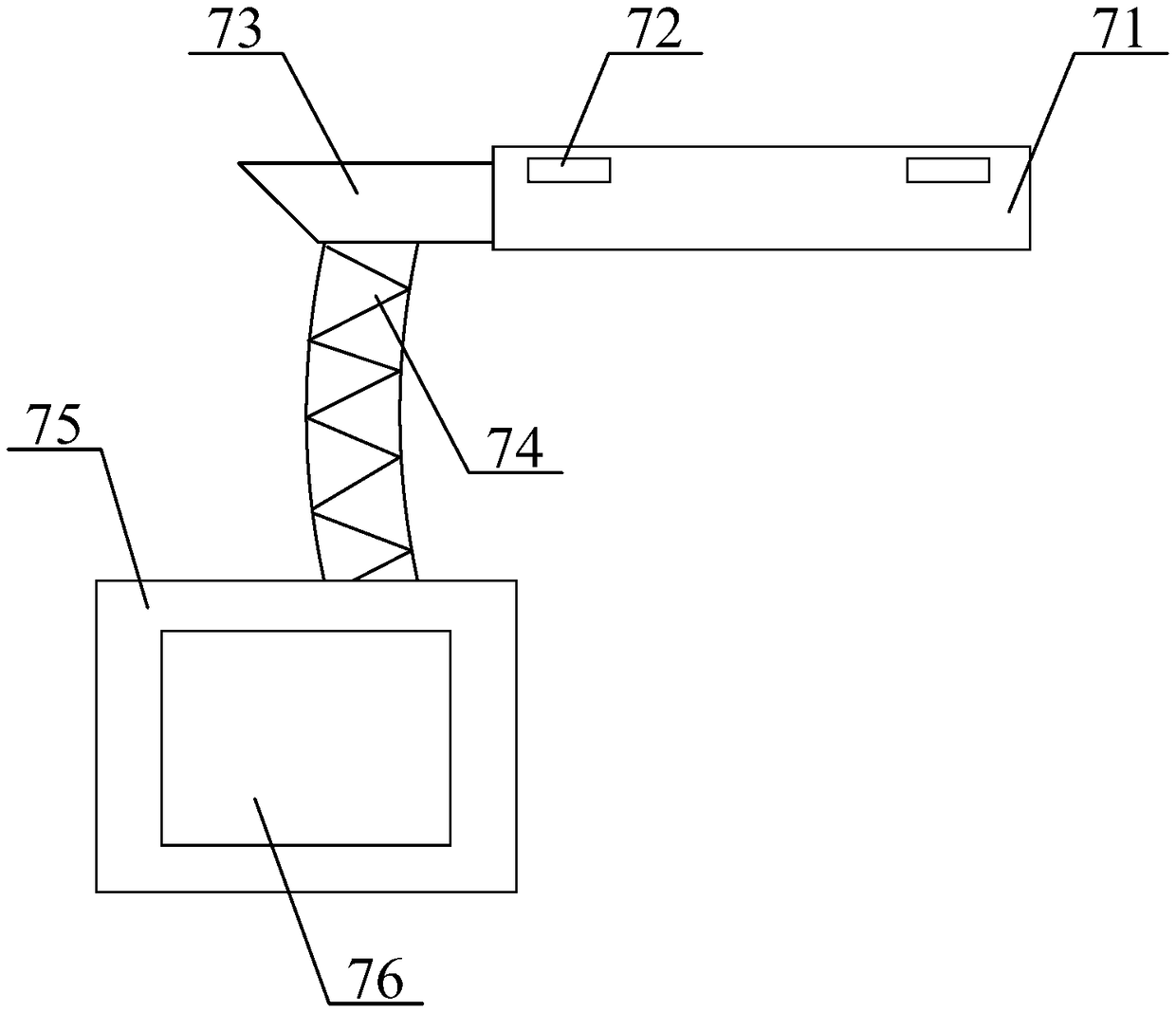
Figure 3
Abstract
Description
technical field
[0001] The invention belongs to the technical field of riveting machines for auto parts processing, and in particular relates to a precision automatic riveting machine. Background technique
[0002] The riveting machine is a new type of riveting equipment developed based on the principle of cold rolling, which refers to the mechanical equipment that can rivet items with rivets. The equipment has compact structure, stable performance, convenient and safe operation. The riveting machine mainly completes the assembly by rotation and pressure. It is mainly used in the occasions where hollow rivets, hollow rivets, and solid rivets are required. The common models include pneumatic, hydraulic, electric, single-head and double-head. The common types are mainly automatic riveting machines, which are mainly aimed at the riveting of semi-hollow riveting machines, which can automatically unload materials, have high riveting efficiency and spin riveting machines. Rivets...
Examples
Embodiment
[0041] as attached figure 1 to attach Figure 6 shown
[0042] The present invention provides a precision automatic riveting machine, which includes a riveting table 1, a tool box 2, a door 3, a support seat 4, an adjusting hand wheel 5, an adjustable and enlarged lighting sleeve structure 6, and a waste recycling operation panel structure 7 , a sliding tool box structure 8, a control cabinet structure 9, a fixed base 10, a support column 11, a riveting head 12, a hydraulic telescopic cylinder 13, a rotating motor 14 and a screw lever 15, and the riveting workbench 1 is bolted to the toolbox 2; the door 3 is respectively hinged on the left and right sides of the front surface of the tool box 2; the support base 4 is bolted to the four corners of the lower surface of the tool box 2; The wheel 5 is threadedly connected to the lower surface of the screw lever 15; the adjustable magnifying lighting sleeve structure 6 is sleeved on the upper position of the outer surface of the s...