
Casting process for directional control valve
A directional control valve and casting process technology, applied in manufacturing tools, casting molding equipment, casting molds, etc., to avoid overheating, ensure appearance quality, and ensure product dimensional accuracy.
Patent Information
- Authority / Receiving Office
- CN · China
- Patent Type
- Applications(China)
- Current Assignee / Owner
- Publication Date
- 2018-10-30
- Estimated Expiration
- Not applicable · inactive patent
Smart Images
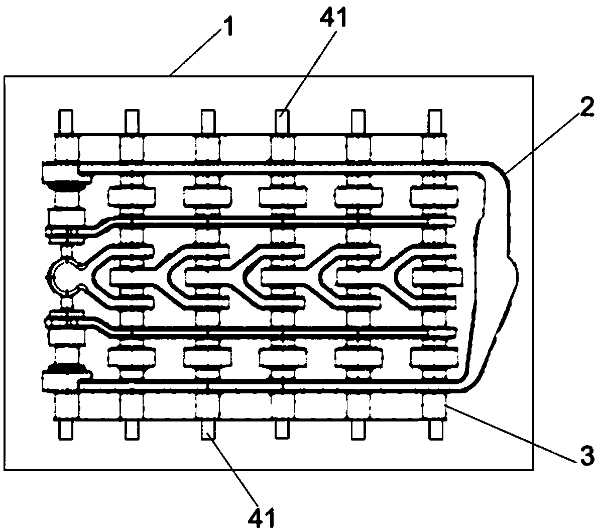
Figure 1 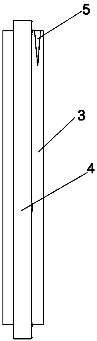
Figure 2
Abstract
Description
technical field
[0001] The invention relates to the technical field of casting, in particular to a casting process of a directional control valve. Background technique
[0002] Directional control valve is a control element used to change the flow direction of gas or liquid in the pipeline. With the development of hydraulic technology, high pressure and large flow have always been an important direction for the development of the hydraulic industry. In recent years, with the increasing tonnage of construction machinery, the hydraulic system of agricultural machinery has higher and higher requirements for directional control valves.
[0003] The Bondioli&Pavesi group company was established in Suzzara, Italy in 1950, and in just a few years it has taken a leading position in the field of drive shafts in the world. Bondioli&Pavesi Group is the first in Italy to provide complete transmission systems in agricultural machinery and equipment, and is constantly expanding its rang...
Examples
Embodiment 1
[0035] The invention provides a manufacturing process of a directional control valve, which mainly includes the following steps:
[0036] S1, molding process (as shown in the figure and figure 2 As shown): make a shell 1, and set a gate with a height of 8 mm and a length of 30 mm on the side of the shell 1; use resin sand molding to make a clay core 2, and set a core bone 4 in the clay core 2 and the ventilation needle 5, and the ventilation needle 5 is set away from the mandrel 4, and the mandrel 4 is made of steel pipe; the mud core 2 is polished after being made, and the two sides of the sand core 2 after polishing The core bone protruding part 41 is provided at the end; the mud core 2 is placed horizontally in the shell 1, and the core bone protruding part 41 is overlapped with the inside of the shell 1; the specific connection structure As follows: the top of the shell 1 is provided with a thermal insulation riser, the shell 1 includes an upper shell and a lower shell, ...
Embodiment 2
[0041] The invention provides a manufacturing process of a directional control valve, which mainly includes the following steps:
[0042] S1, molding process (as shown in the figure and figure 2 As shown): make a shell 1, and set a gate with a height of 8 mm and a length of 30 mm on the side of the shell 1; use resin sand molding to make a clay core 2, and set a core bone 4 in the clay core 2 and the ventilation needle 5, and the ventilation needle 5 is set away from the mandrel 4, and the mandrel 4 is made of steel pipe; the mud core 2 is polished after being made, and the two sides of the sand core 2 after polishing The core bone protruding part 41 is provided at the end; the mud core 2 is placed horizontally in the shell 1, and the core bone protruding part 41 is overlapped with the inside of the shell 1; the specific connection structure As follows: the top of the shell 1 is provided with a thermal insulation riser, the shell 1 includes an upper shell and a lower shell, ...
Embodiment 3
[0047] The invention provides a manufacturing process of a directional control valve, which mainly includes the following steps:
[0048] S1, molding process (as shown in the figure and figure 2 As shown): make a shell 1, and set a gate with a height of 8 mm and a length of 30 mm on the side of the shell 1; use resin sand molding to make a clay core 2, and set a core bone 4 in the clay core 2 and the ventilation needle 5, and the ventilation needle 5 is set away from the mandrel 4, and the mandrel 4 is made of steel pipe; the mud core 2 is polished after being made, and the two sides of the sand core 2 after polishing The core bone protruding part 41 is provided at the end; the mud core 2 is placed horizontally in the shell 1, and the core bone protruding part 41 is overlapped with the inside of the shell 1; the specific connection structure As follows: the top of the shell 1 is provided with a thermal insulation riser, the shell 1 includes an upper shell and a lower shell, ...