
Parallel centrifugal fan
A centrifugal fan and base technology, which is applied to mechanical equipment, machines/engines, liquid fuel engines, etc., can solve the problems of large pressure loss, limited axial length of ordinary centrifugal fans, and low efficiency.
Patent Information
- Authority / Receiving Office
- CN · China
- Patent Type
- Applications(China)
- Current Assignee / Owner
- Publication Date
- 2018-11-20
Smart Images
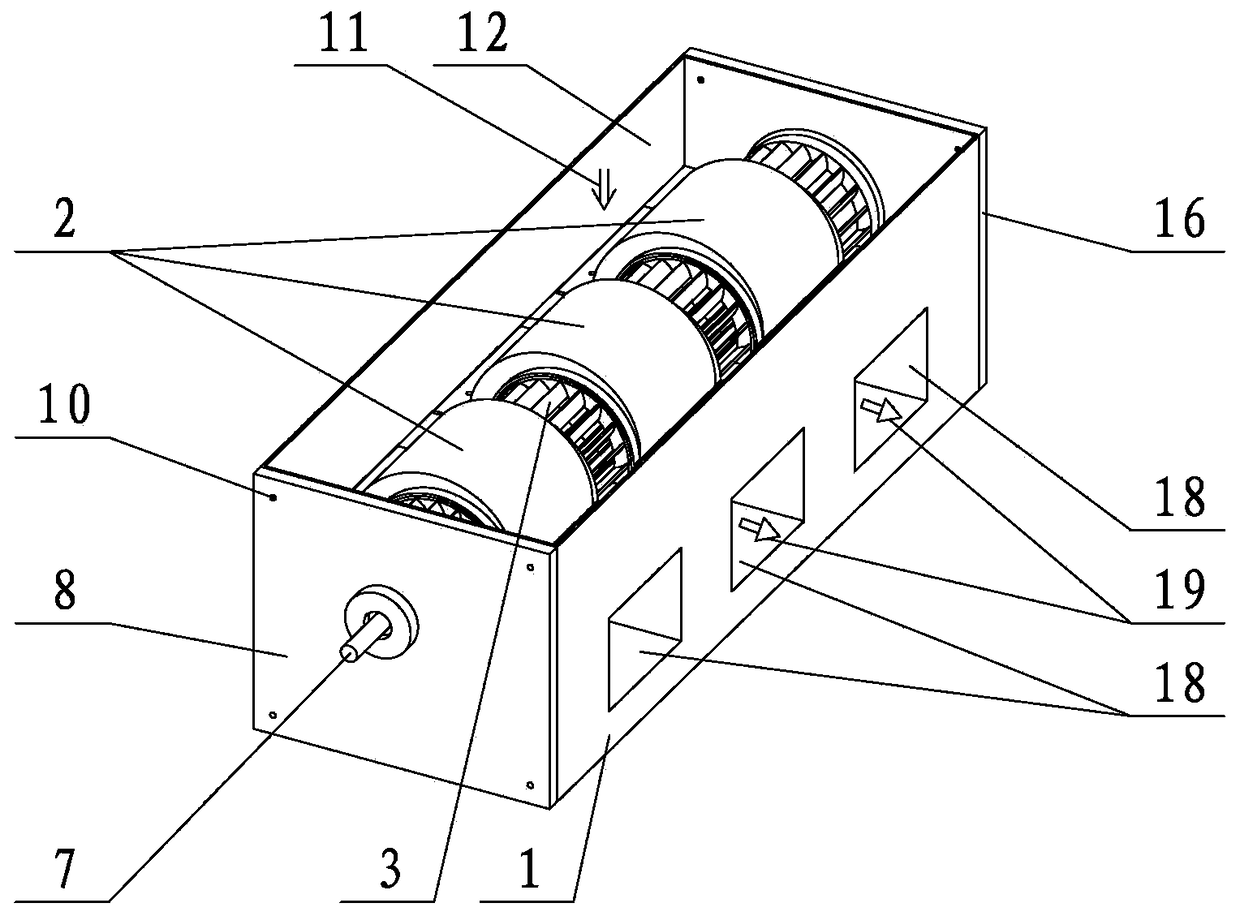
Figure 1 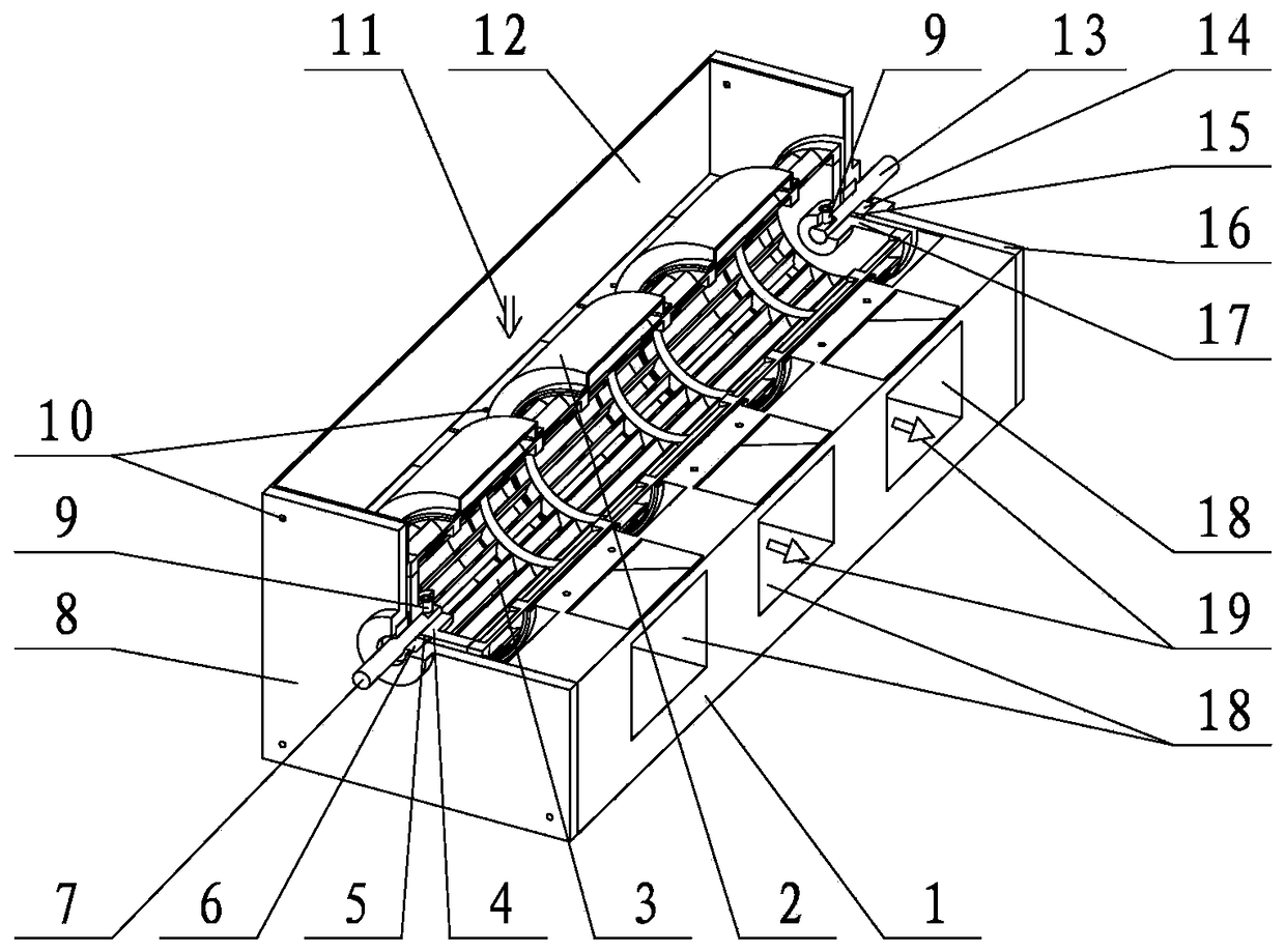
Figure 2 
Figure 3
Abstract
Description
technical field
[0001] The invention relates to a parallel centrifugal fan, which relates to a fan, in particular to a parallel centrifugal fan with unlimited axial length. Background technique
[0002] The types of fans commonly used in home appliances include axial fans, cross-flow fans, and centrifugal fans. Its typical application product examples are vertical fans using axial fans, range hoods using centrifugal fans, and indoor units of air conditioners using cross-flow fans. Axial flow fans are characterized by large flow, low pressure, and high noise. The structure of the axial flow fan is simple.
[0003] The cross-flow fan is characterized by moderate flow, moderate pressure and low noise. The axial length of the cross-flow fan is not limited, and the airflow at the air outlet is evenly distributed along the axial direction of the cross-flow fan. Compared with the axial flow fan, the airflow of the cross-flow fan flows through the impeller, and the airflow is af...
Examples
Embodiment Construction
[0040] The present invention is further described below in conjunction with accompanying drawing.
[0041] refer to figure 1 , figure 2 , Figure 18 , Figure 19 , The centrifugal fan includes a base part and an impeller part. The impeller part is installed in the inner cavity of the machine base part, and the motor is installed at one axial end of the machine base part. The base 1 of the base component is axially distributed with several confluence volute plates 23 and several centrifugal volute plates 57, and the confluence volute plates 23 and centrifugal volute plates 57 are arranged at intervals one by one along the axial direction. A centrifugal volute inner cavity 59 is formed between the centrifugal guide volute 2 of several machine base parts and the centrifugal volute plate 57 of the machine base 1, and the confluence volute plate 23 of the machine base 1 radially inwardly forms the inner cavity of the confluence volute. Cavity 46. The confluence volute inner ...