
Method for assembling high and low temperature vacuum stepping motor
A low-temperature vacuum, stepper motor technology, used in the manufacture of motor generators, electrical components, electromechanical devices, etc., can solve problems such as uneven pressure on magnetic steel, damage to stator or motor housing, and excessive coaxiality. , to achieve the effect of ensuring accuracy and simple installation
Patent Information
- Authority / Receiving Office
- CN · China
- Current Assignee / Owner
- Publication Date
- 2019-07-09
Smart Images
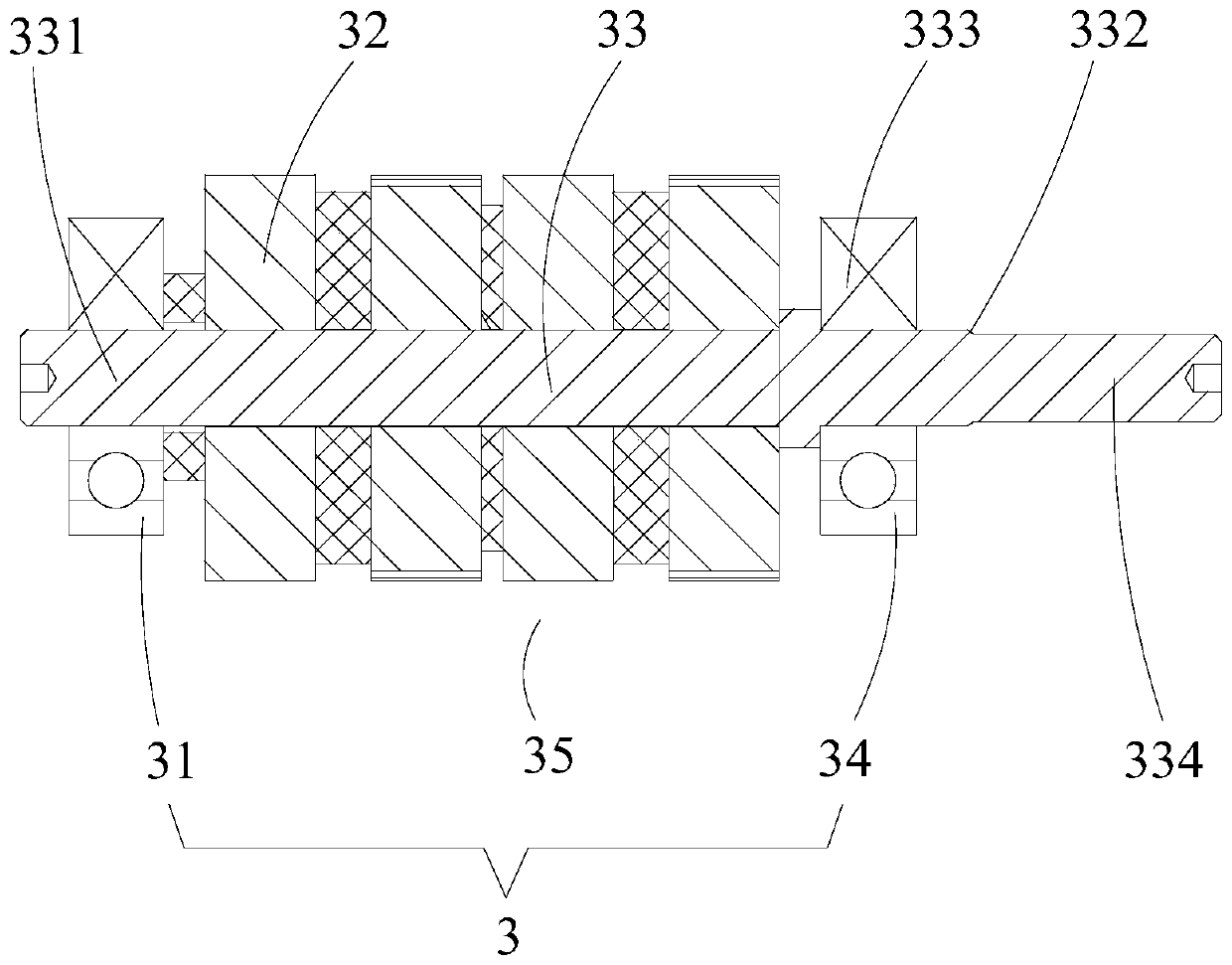
Figure 1 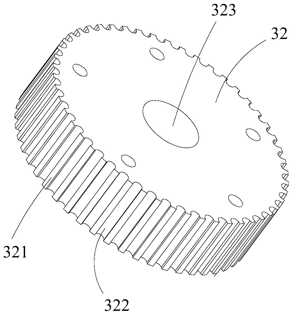
Figure 2 
Figure 3
Abstract
Description
technical field
[0001] The invention relates to the technical field of stepping motor assembly, in particular to a method for assembling a high and low temperature vacuum stepping motor. Background technique
[0002] Such as figure 1 and 2 As shown, the current high and low temperature stepping motor rotor 3 is composed of main parts such as a rotating shaft 33 and several iron cores 32. The outer surface of the iron core 32 is provided with several rotating teeth 321. On the same iron core 32, adjacent rotating teeth 321 forms a groove 322 shape; the shaft 33 is coaxially provided with a journal head end 331 , a journal tail end 333 and a shaft extension 334 , and the journal tail end 333 is arranged on the journal head end 331 and the shaft extension 334 Between, the diameter of the journal head end 331 and the journal end end 333 is the same, the diameter of the shaft extension part 334 is smaller than the diameter of the journal end end 333, and the connection between ...
Examples
Embodiment 1
[0082] Such as Figure 1-8 As shown, a method for assembling a high and low temperature vacuum stepping motor includes the following steps:
[0083] Step 1, install the rotating shaft 33 on the first tooling 12, the first tooling 12 is installed on the moving plate 114, install the iron core 32 on the second tooling 13, and the second tooling 13 is installed on the support 11 Above, the electric cylinder 2 is connected to the moving plate 114, and the electric cylinder 2 is arranged vertically. The moving plate 114 slides and fits with the support 11 along the axial direction of the electric cylinder 2. The rotating shaft 33, The iron core 32 and the electric cylinder 2 are arranged coaxially, and the electric cylinder 2 drives the moving plate 114 to slide relative to the support 11 to complete the assembly of the rotating shaft 33 and the iron core 32 to form a rotor Iron core assembly 35;
[0084] Step 2, remove the second tooling 13, and remove the rotor core assembly 35...
Embodiment 2
[0091] Such as Figure 1-8 As shown, a method for assembling a high and low temperature vacuum stepping motor as described in Embodiment 1, the electric cylinder 2 is connected with a control system 6, and the control system 6 is used to control the action of the electric cylinder 2 , the control system 6 is electrically connected to the electric cylinder 2, the control system 6 includes a control module 61 and an HMI module 62, wherein,
[0092] The HMI module 62 is used to provide an interactive interface between the control system 6 and the user, including receiving user instructions, transmitting the user-input instructions to the control module 61, and displaying the electric cylinder 2 displacement results;
[0093] The control module 61 controls the electric cylinder 2 to drive the moving plate 114 to a predetermined position according to the instruction, and the control module 61 is electrically connected with the electric cylinder 2 and the HMI module 62 respectively...
Embodiment 3
[0100] Such as Figure 1-8 As shown, a method for assembling a high and low temperature vacuum stepping motor as described in Embodiment 1 or 2, the support 11 includes an upper seat plate 111 and a lower seat plate 112, and the upper seat plate 111 and the lower seat plate 112 A sliding rod 113 is connected between the seat plates 112, and the moving plate 114 slides and fits with the sliding rod 113 along the axial direction of the electric cylinder. The electric cylinder 2 includes a cylinder barrel 21 and a movable rod 22. The upper seat plate 111 is connected with the cylinder 21 , and the moving plate 114 is connected with the movable rod 22 .
[0101] On the basis of the above, in a further preferred manner, there are four sliding rods 113, all the sliding rods 113 are distributed on the same circumference on the lower seat plate 112, and all the sliding rods 113 are parallel to each other.
[0102] Four sliding rods 113 are distributed on the circumference, and all th...