
Nodeless screen printing plate based on stainless steel plate
A stainless steel plate, no node technology, applied in screen printing machines, rotary printing machines, printing, etc., can solve the problems of affecting the life of screen printing, leakage of printing debris, and great influence on strength, etc., to achieve good current collection and Transmission ability, small printing resistance, good surface smoothness
Patent Information
- Authority / Receiving Office
- CN · China
- Current Assignee / Owner
- Publication Date
- 2019-09-24
- Estimated Expiration
- Not applicable · inactive patent
Smart Images
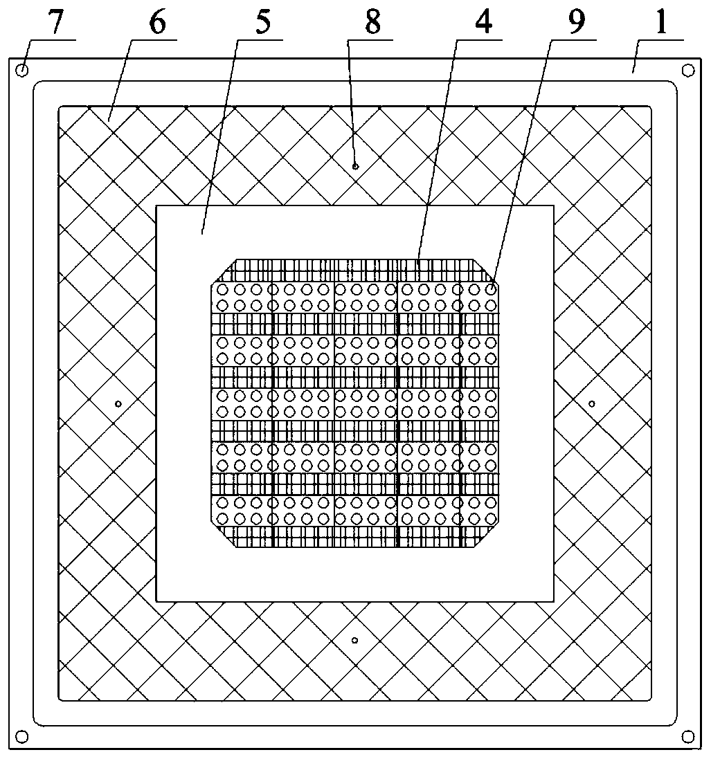
Figure 1 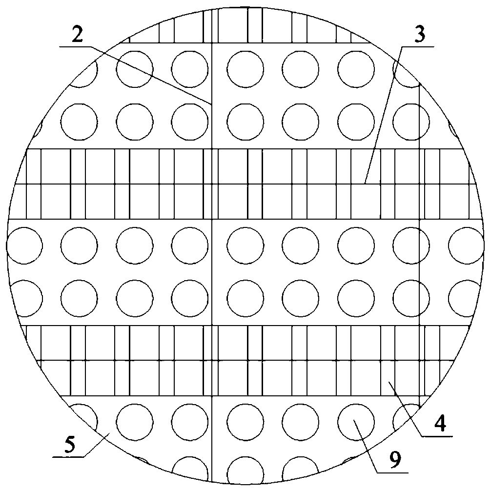
Figure 2 
Figure 3
Abstract
Description
technical field
[0001] The invention belongs to the technical field of printing equipment and relates to a screen, in particular to a nodeless screen based on a stainless steel plate. Background technique
[0002] As the problem of environmental pollution becomes more and more serious, many countries begin to develop new green new energy sources to reduce environmental pollution, among which solar energy research occupies an important position. Solar cells can convert the sun's light energy into electrical energy, and this conversion will not cause any pollution to the environment. Therefore, solar cells, as one of the core technologies of solar energy research, have been rapidly developed. Screen printing is the last process in the entire battery sheet manufacturing process. By using the basic principle of the hollowed out part of the screen to penetrate the slurry and the non-hollowed part to be impermeable to the slurry, a layer of conductive paste is printed on the front...
Examples
Embodiment Construction
[0020] Below in conjunction with accompanying drawing and specific embodiment the present invention is described in detail:
[0021] 1. Specific examples
[0022] A nodeless screen based on a stainless steel plate, including a screen frame 1 and a carrier stretched inside the screen frame 1. A group of parallel main grid lines 2 and a group of parallel auxiliary grid lines are arranged at the center of the carrier. 3 and a group of via holes 4 for passing the slurry, the main grid line 2 and the sub grid line 3 are arranged vertically, such as figure 1 with figure 2 As shown, the main grid lines 2 are arranged vertically, the auxiliary grid lines 3 are arranged horizontally, the via holes 4 are rectangular holes, and a group of rectangular holes are opened on the periphery of each auxiliary grid line 3 along the length direction, and the auxiliary grid lines 3 are located at At the center of the length side of the rectangular hole, the line width of the auxiliary grid line ...