
A collision gap self-coordinating device
A self-coordination and collision technology, applied in the direction of building types, buildings, building components, etc., can solve the problems of narrow vibration reduction frequency band, large mass of collision damper, noise pollution, etc., achieve self-adaptation of excitation intensity, reduce bad vibration, The effect of improving the vibration damping effect
Patent Information
- Authority / Receiving Office
- CN · China
- Patent Type
- Patents(China)
- Current Assignee / Owner
- Publication Date
- 2020-08-18
Smart Images
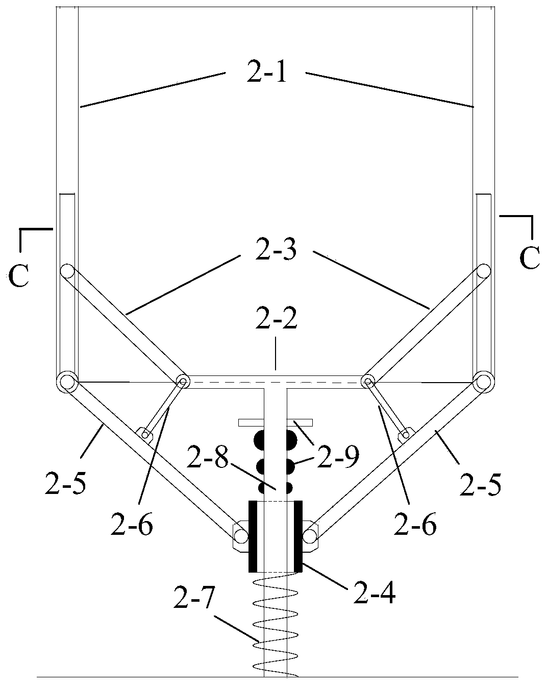
Figure 1 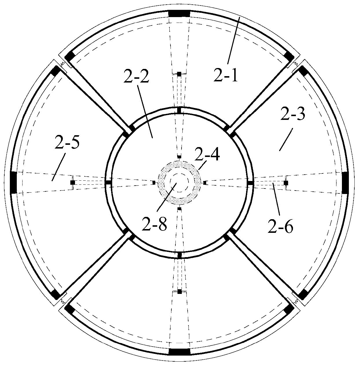
Figure 2 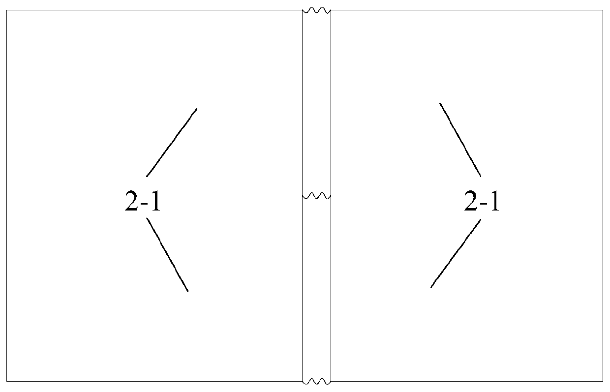
Figure 3
Abstract
Description
Technical field
[0001] The invention belongs to the field of civil engineering structure vibration control, and specifically relates to a collision gap self-coordination device. Background technique
[0002] With the rapid development of the social economy, the size of the building structure is increasing, from high-rise buildings to super high-rise buildings. At the same time, the threats to high-rise buildings such as earthquakes and wind loads are increasing day by day. In recent years, in previous major earthquakes and wind disasters, accidents of structural collapse and damage have occurred from time to time, and economic losses are incalculable. Therefore, the development and application of structural vibration reduction technology is an inevitable trend.
[0003] Passive control technology has the characteristics of maturity, high cost performance, high reliability and easy maintenance, and is widely used in structural vibration reduction. Among them, the collision damper...
Examples
Embodiment
[0030] A collision gap self-coordination device, such as figure 1 , 2 As shown, it consists of a limit plate 2-1, a fixed chassis 2-2, a fan-shaped movable edge plate 2-3, a reset slider 2-4, a support member 2-5, a conversion rod 2-6, and a return spring 2-7 , Composed of fixed rods 2-8 and blocking members 2-9.
[0031] The limit plate 2-1 encloses the collision area, and the limit plate 2-1 is an arc-shaped vertical plate. In this embodiment, four limit plates 2-1 are arranged to enclose a cylindrical structure, such as image 3 , The two adjacent limit plates 2-1 are softly connected by three upper, middle and lower springs. The lower end of each limit plate is connected to the reset slider 2-4 through the support member 2-5, and the reset slider 2- 4 Nested on the fixed rod 2-8, the lower end is provided with a return spring 2-7, the upper part of the fixed rod is provided with a blocking member 2-9, the support member 2-5 is provided with a steering plate in the middle posi...