
A teaching demonstration device and teaching method for turbidity flow deposition experiments
A demonstration device and turbidity flow technology, applied in teaching models, educational tools, instruments, etc., can solve the problems of inconvenient simulation of deposition characteristics, uneven mixing, inconvenient fixing of water tanks, etc., and achieve the effect of convenient comparison and observation and reduction of preparation procedures
Patent Information
- Authority / Receiving Office
- CN · China
- Patent Type
- Patents(China)
- Current Assignee / Owner
- Publication Date
- 2021-05-07
Smart Images
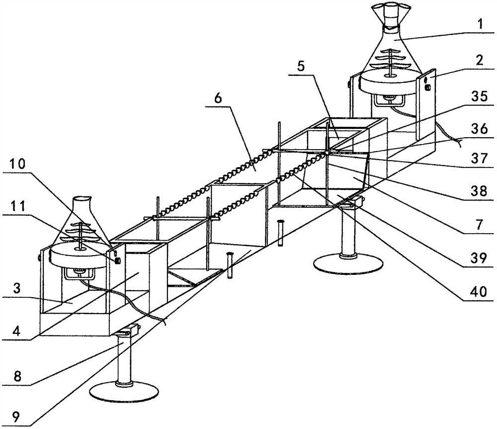
Figure 1 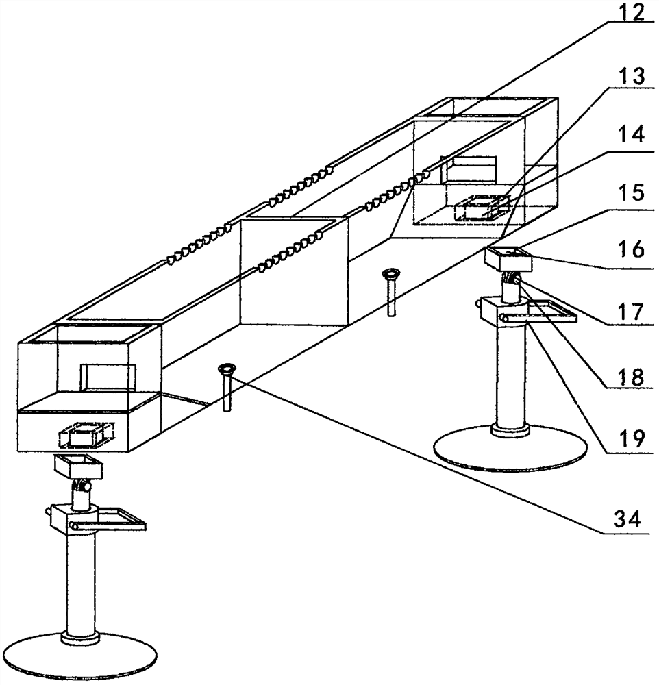
Figure 2 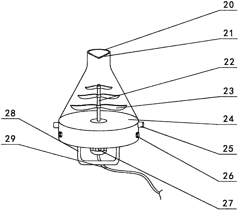
Figure 3
Abstract
Description
technical field
[0001] The invention relates to an experiment demonstration device, in particular to a turbidity flow deposition experiment teaching demonstration device. Background technique
[0002] The generalized turbidity current is underwater gravity flow. Turbidity current in a narrow sense is a special form of underwater gravity flow, which is a mixture of water and a large amount of sand and mud supported by a self-suspended turbulent flow mechanism, which moves at the bottom of the water (deep water area below the wave base) density flow. Turbidity currents mostly occur in continental margins and are often triggered by factors such as earthquakes, landslides, and storm waves. They are an important mechanism for transporting terrigenous materials from shallow seas to deep seas, and can form turbidity current deposits on continental margins or ocean basins. Paleoturbidity current deposits formed during geological periods often become oil reservoirs. As a unique ty...
Examples
Embodiment Construction
[0057] The present invention is described in further detail now in conjunction with accompanying drawing. These drawings are all simplified schematic diagrams, which only illustrate the basic structure of the present invention in a schematic manner, so they only show the configurations related to the present invention.
[0058] combined with figure 1 --The structure given in 4 is a teaching and demonstration device for turbidity current deposition experiments. The tank body is composed of tanks A6 and B9 arranged vertically opposite each other. Both tanks A6 and B9 are made of transparent plastic or made of glass material, and the lower surface of the water tank A6 and the water tank B9 are respectively provided with a drain 34, and the described drain 34 is a plugging spring type drain or a plugging flap type drain, in the described The opposite end of the water tank A6 to the water tank B9 is provided with a dividing plate 12, and the other end of the water tank A6 and the ...