
propeller fan
一种螺旋桨、风扇的技术,应用在螺旋桨式风扇领域,能够解决鼓风声音级别上升、无法解决不适感等问题,达到抑制噪声增大、抑制不适感、抑制振动增大的效果
Patent Information
- Authority / Receiving Office
- CN · China
- Patent Type
- Patents(China)
- Current Assignee / Owner
- Publication Date
- 2021-05-28
Smart Images
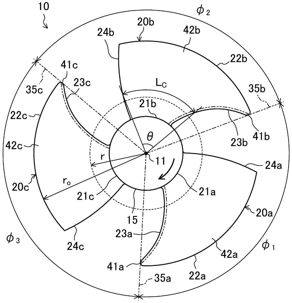
Figure 1 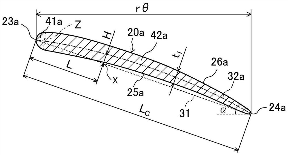
Figure 2 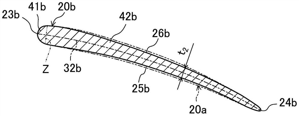
Figure 3
Abstract
Description
technical field
[0001] The present invention relates to a propeller fan used in blowers and the like. Background technique
[0002] Heretofore, propeller fans have been widely used for blowers and the like. The noise generated by the rotation of the propeller fan includes a periodic sound called NZ noise (NZ noise). The frequency of the NZ noise is the product of the number of blades and the rotational speed of the propeller fan. Patent Document 1 discloses a technique of arranging blades at unequal pitches in the circumferential direction of a propeller fan in order to suppress discomfort of a user or the like caused by the NZ noise.
[0003] Here, if blades of the same mass are arranged at unequal intervals in the circumferential direction of the propeller fan, the rotation of the propeller fan will lose balance. Specifically, the center of gravity of the propeller fan is separated from the central axis of rotation of the propeller fan. Furthermore, if the propeller fa...
Examples
no. 1 approach
[0039] The first embodiment will be described. The propeller fan 10 of this embodiment is an axial flow fan. The propeller fan 10 is installed, for example, in a heat source unit of an air conditioner, and is used to supply outdoor air to a heat source side heat exchanger.
[0040] -Structure of Propeller Fan-
[0041] Such as figure 1 As shown, the propeller fan 10 of this embodiment includes a hub 15 and three blades 20a, 20b, 20c. One hub 15 is integrally formed with three blades 20a to 20c. The propeller fan 10 is made of resin.
[0042] The hub 15 is formed in a cylindrical shape with a closed front end. The hub 15 is mounted on the drive shaft of the fan motor. The center axis of the hub 15 is the rotation center axis 11 of the propeller fan 10 .
[0043] The blades 20 a to 20 c are arranged to protrude outward from the outer peripheral surface of the hub 15 . The three blades 20 a to 20 c are arranged at predetermined intervals in the circumferential direction o...
no. 2 approach
[0087] A second embodiment will be described. In the propeller fan 10 of the present embodiment, the shapes of the blades 20 a to 20 c are changed from the propeller fan 10 of the first embodiment. Here, differences between propeller fan 10 of the present embodiment and propeller fan 10 of the first embodiment will be described.
[0088] Such as Figure 4A ~ Figure 4CAs shown, swelling portions 45a, 45b, and 45c are formed on the blades 20a to 20c of the present embodiment. The bulging portions 45a to 45c are portions swollen toward the positive pressure surfaces 25a to 25c of the blades 20a to 20c, and extend along the leading edge portions 41a to 41c across the entire length of the leading edge portions 41a to 41c. The surfaces of the raised portions 45a to 45c are convex surfaces that are smoothly connected to the surfaces of the regions adjacent to the raised portions 45a to 45c of the blades 20a to 20c. The shapes of the swelling parts 45a to 45c of the respective blad...
other Embodiment approach
[0091] In the propeller fan 10 of each of the above-mentioned embodiments, the number of the blades 20 a to 20 c may be an odd number of five or more. Moreover, in the propeller fan 10 of each embodiment mentioned above, the number of blades 20a-20c may be an even number.
[0092] In addition, the propeller fan 10 of each of the above-mentioned embodiments may be such that not all blades but some blades have different circumferential angles and masses.
[0093] Furthermore, in the propeller fan 10 according to the first embodiment described above, the shapes of the respective arcs 32 a to 32 c of the respective blades 20 a to 20 c and the respective projections on a plane perpendicular to the rotation central axis 11 of the propeller fan 10 The shape in the drawing and the shapes of the respective front edge portions 41 a to 41 c may be consistent with each other. Regarding the "shape of the arcs 32a to 32c", "shape of the projected view projected on a plane perpendicular to ...