
Automatic packaging machine for concrete products for maritime work
A concrete product, automatic packaging machine technology, applied in the direction of packaging, transportation and packaging, packaging item types, etc., can solve the problems of inability to adjust the height of the packaging bag, inconvenient packaging, dust scattering, etc., to avoid pollution, facilitate packaging, The effect of avoiding waste
Patent Information
- Authority / Receiving Office
- CN · China
- Current Assignee / Owner
- Publication Date
- 2020-02-07
- Estimated Expiration
- Not applicable · inactive patent
Smart Images
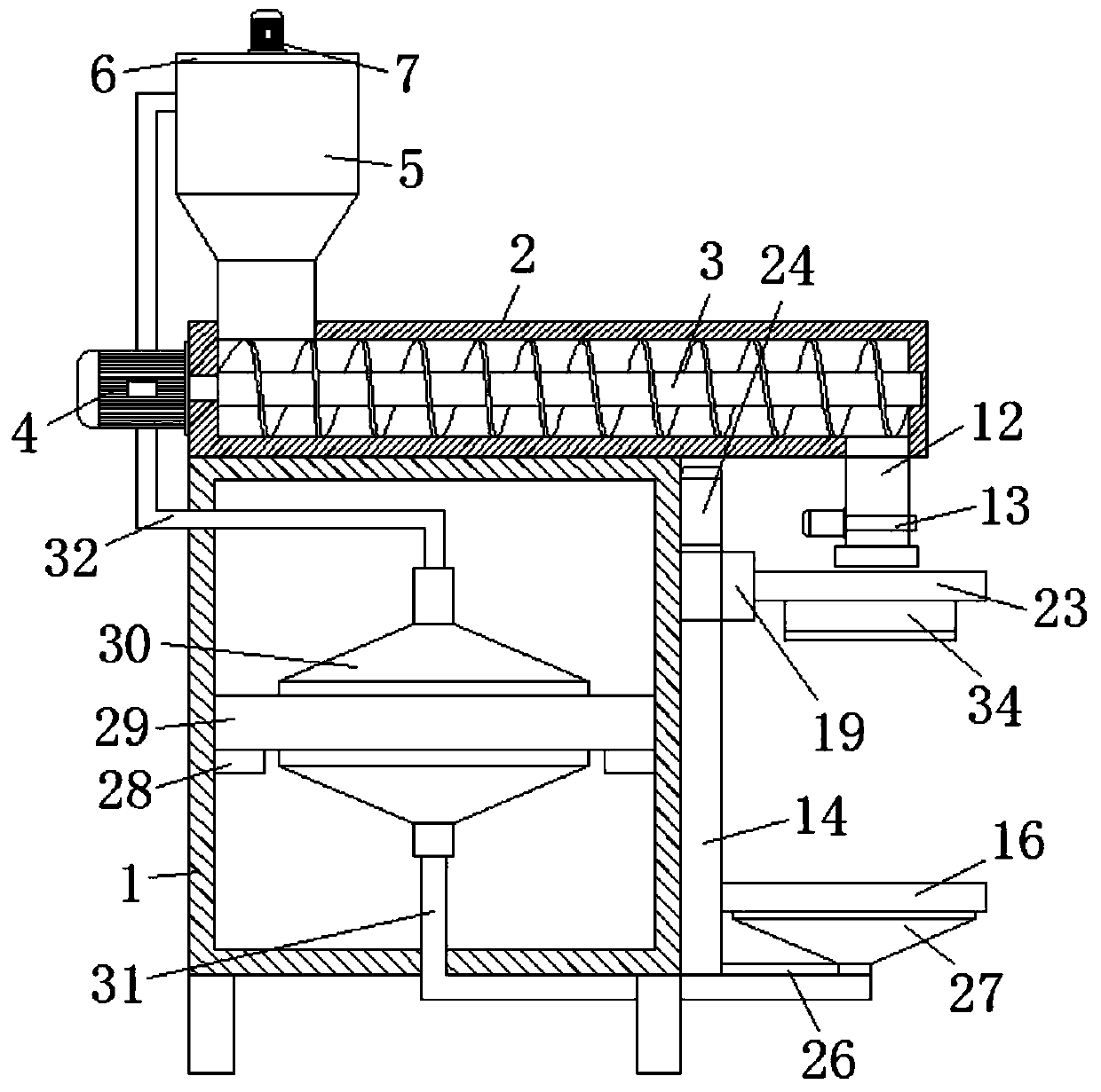
Figure 1 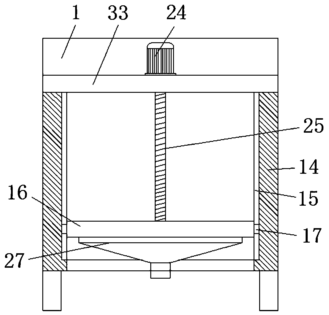
Figure 2 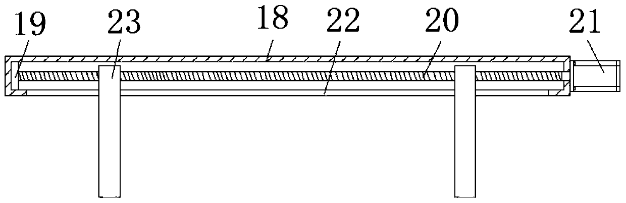
Figure 3
Abstract
Description
technical field
[0001] The invention relates to the related technical field of packaging machines for concrete products for marine engineering, in particular to an automatic packaging machine for concrete products for marine engineering. Background technique
[0002] Marine concrete is used in marine engineering. Marine concrete has high workability and high durability. Marine concrete belongs to high-performance concrete. Because of the needs of transportation or use, it often needs to be packaged with packaging equipment. The existing The packaging machine cannot adjust the height according to the packaging bags of different specifications, which is inconvenient for packaging. At the same time, during packaging, dust is often scattered in the air, causing dust, polluting the air, and causing waste. The design here An automatic packaging machine for marine concrete products is developed in order to solve the above problems. Contents of the invention
[0003] The object o...
Examples
Embodiment 1
[0031] see Figure 1-5, this embodiment provides an automatic packaging machine for marine concrete products, including an installation box 1, the upper surface of the installation box 1 is fixedly connected with a delivery cylinder 2, and the inside of the delivery cylinder 2 is rotatably connected with a screw conveyor shaft 3, and the screw conveyor The middle part of the rear surface of the shaft 3 is fixedly connected with the first motor 4, and the output end of the first motor 4 traverses through the conveying cylinder 2 and is fixedly connected with one end of the screw conveying shaft 3, and the end of the conveying cylinder 2 away from the first motor 4 is lowered The surface is fixedly connected with a discharge cylinder 12, and the discharge cylinder 12 is connected with the conveying cylinder 2, and the upper surface of one end corresponding to the first motor 4 on the conveying cylinder 2 is fixedly connected with a hopper 5, and the hopper 5 is connected with the...
Embodiment 2
[0034] see Figure 1-5 On the basis of Embodiment 1, a further improvement has been made: the interior of the hopper 5 is fixedly connected with a reinforcement frame 8, the top of the hopper 5 is fixedly connected with a support frame 6, and the reinforcement frame 8 and the support frame 6 are rotatably connected with a rotating shaft 9 , and the rotating shaft 9 longitudinally runs through the reinforcing frame 8 and the supporting frame 6, the middle part of the upper surface of the supporting frame 6 is fixedly connected with the second motor 7, and the output end of the second motor 7 is fixedly connected with the top end of the rotating shaft 9, the rotating shaft The bottom end of 9 is fixedly connected with stirring paddle 11 below the reinforcement frame 8, and the stirring roller 10 is fixedly connected between the support frame 6 and the reinforcement frame 8 on the outer wall of the rotating shaft 9, and the stirring rollers 10 are annularly distributed. Control t...