
Hydraulic oil tank with external filtering structure
A technology of hydraulic oil tank and filter structure, applied in the direction of oil supply tank device, fluid pressure actuating device, fluid pressure actuating system components, etc., can solve problems such as hidden safety hazards, high energy consumption, pollution of the surrounding environment, etc. , Easy to adjust, low energy consumption
Patent Information
- Authority / Receiving Office
- CN · China
- Current Assignee / Owner
- Publication Date
- 2020-02-14
Smart Images
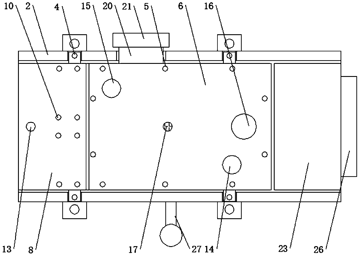
Figure 1 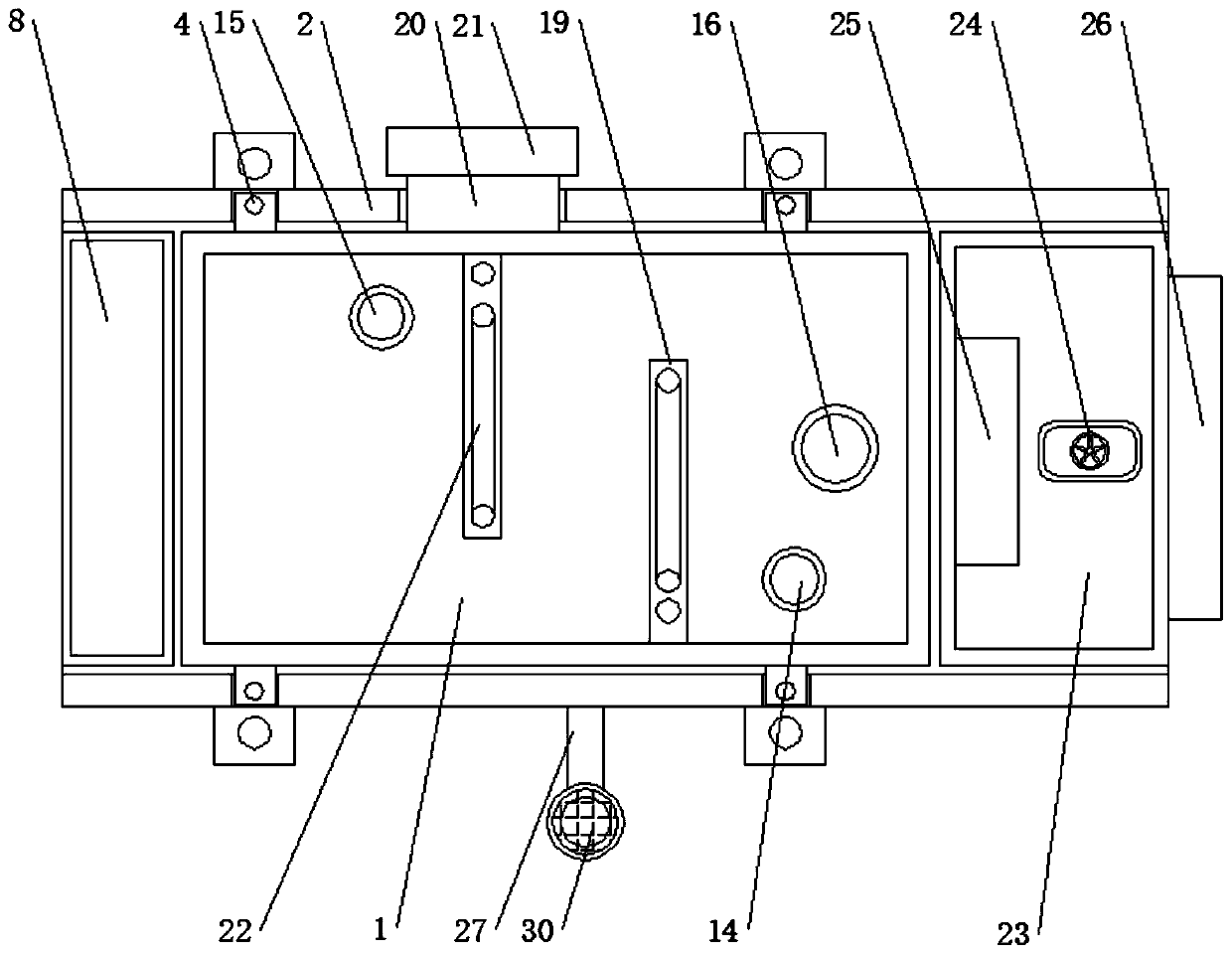
Figure 2 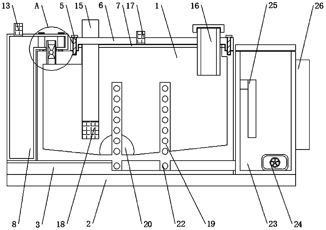
Figure 3
Abstract
Description
technical field
[0001] The invention relates to the technical field of hydraulic oil tanks, in particular to a hydraulic oil tank with an external filtering structure. Background technique
[0002] The hydraulic oil tank refers to the container used to store the oil required to ensure the operation of the hydraulic system. In addition, it also plays a role in cooling the oil and allowing the air in the oil to escape.
[0003] The existing hydraulic oil tank can only play the role of precipitating impurities. After the hydraulic system has been running for a long time, a large amount of impurities will accumulate inside the oil tank, resulting in a gradual decrease in the operating efficiency of the hydraulic system. Preheating, this kind of preheating method has high energy consumption and low efficiency, and cannot quickly and effectively increase the temperature of the oil, and the existing hydraulic oil tank will overflow when the operation is wrong, the reason is that th...
Examples
Embodiment Construction
[0028] The following will clearly and completely describe the technical solutions in the embodiments of the present invention with reference to the accompanying drawings in the embodiments of the present invention. Obviously, the described embodiments are only some, not all, embodiments of the present invention. Based on the embodiments of the present invention, all other embodiments obtained by persons of ordinary skill in the art without making creative efforts belong to the protection scope of the present invention.
[0029] see Figure 1-7 , the present invention provides a technical solution: a hydraulic oil tank with an external filter structure, such as figure 1 , image 3 and Figure 4 As shown, a bracket 2 is arranged outside the bottom of the hydraulic oil tank 1, and a rubber pad 3 is arranged between the hydraulic oil tank 1 and the bracket 2. At the same time, the oil discharge port 20 is arranged on the rear side of the left partition 19, so that the oil can b...