
Novel cement mortar stirring device
A cement mortar and mixing device technology, applied in cement mixing devices, measuring devices, clay preparation devices, etc., can solve problems such as waste of materials, impact on accuracy, unreasonable structural design, etc.
Patent Information
- Authority / Receiving Office
- CN · China
- Current Assignee / Owner
- Publication Date
- 2020-02-18
- Estimated Expiration
- Not applicable · inactive patent
Smart Images
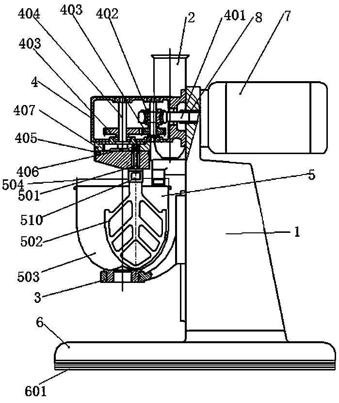
Figure 1 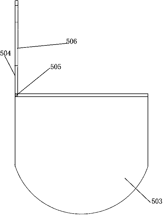
Figure 2 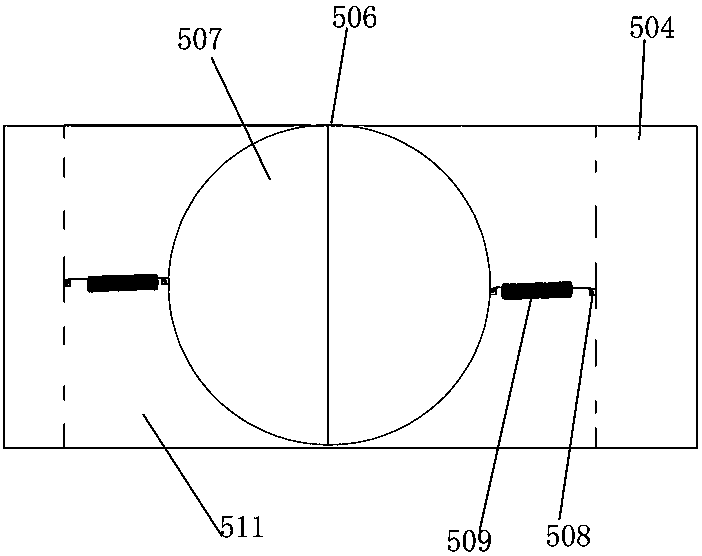
Figure 3
Abstract
Description
technical field
[0001] The invention relates to the technical field of inspection equipment, in particular to a novel cement mortar mixing device. Background technique
[0002] The cement mortar mixing device is a kind of equipment used to stir the cement mortar mixture according to the speed and time required by the cement mortar strength inspection specification. The raw materials of the cement mortar include cement, standard sand and water. The existing cement mortar The structural design of the mortar mixing device is unreasonable. When the material is stirred, due to the large stirring range of the stirring paddle, the material is easily overflowed from the mixing box, resulting in waste of material, which has a certain impact on the accuracy of the test. The above problems can be solved by installing a box cover on the mixing box, but the installation of the box cover will cause the stirring paddle to be unable to enter the box body, and the box cover must be opened to...
Examples
Embodiment 1
[0016] Embodiment 1: A new type of cement mortar mixing device, including a fuselage 1, a feeding box 2, a transmission box assembly 4, a stirring assembly 5 and a base 6, and the side end of the fuselage 1 is fixedly equipped with a feeding box 2, so One end of the fuselage 1 is provided with a transmission box assembly 4 , and the bottom end of the transmission box assembly 4 is provided with a stirring assembly 5 and is in transmission connection with it. The fuselage 1 is arranged on a base 6 .
Embodiment 2
[0017] Embodiment 2: the stirring assembly 5 includes a stirring shaft 501, a stirring paddle 502 and a stirring box 503, the bottom end of the stirring shaft 501 is equipped with a stirring paddle 502, and the upper end of the stirring box 503 is communicated with the charging box 2 through a delivery pipeline, The mixing box 503 is equipped with a protective box cover 504, the mixing box 503 is located on the support 3, the protective box cover 504 is closed and connected with the mixing box 503 through a pin 505, and the protective box cover 504 is opened There is a relief hole 506, the relief hole 506 is equipped with a relief clip cover 507, the two sides of the relief hole 506 are provided with cavity grooves 511, and the side ends of the protective case cover 504 and the inner wall of the cavity groove 511 are both A positioning hook 508 is installed, and a telescopic spring 509 runs through the positioning hook 508 and is hooked to it. The stirring shaft 501 is equipped...
Embodiment 3
[0018] Embodiment 3: An anti-slip layer 601 is installed at the bottom of the base 6, and the anti-slip layer 601 is integrally formed by injection molding of polyurethane rubber. The rest of the technical solutions are the same as those in Embodiments 1 and 2.