
An Improved Textile Roller
An improved roller technology, which is applied in textiles and papermaking, spinning machines, drafting equipment, etc., can solve the problems of complex operation, no mention of the problem of rollers, and the inability to automatically polymerize and press the yarn, so as to achieve convenient combined operation , High stability effect
Patent Information
- Authority / Receiving Office
- CN · China
- Patent Type
- Patents(China)
- Current Assignee / Owner
- Publication Date
- 2021-06-18
Smart Images
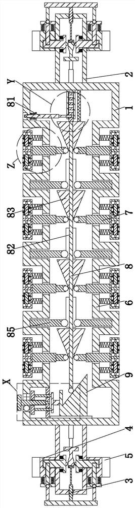
Figure 1 
Figure 2 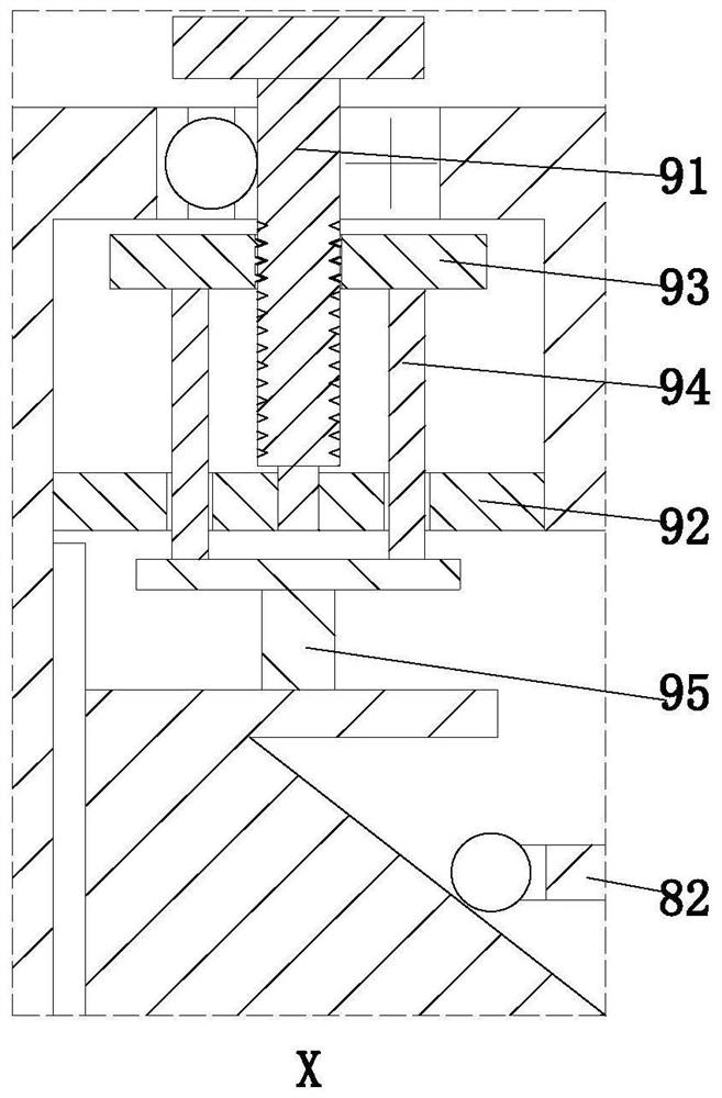
Figure 3
Abstract
Description
technical field
[0001] The invention relates to the technical field of injection molding, in particular to an improved textile roller. Background technique
[0002] Roller is a cylindrical rotating part that plays the role of feeding, drafting, output, etc. in textile machinery. It is widely used in drafting, carding, conveying and other mechanisms. The roller usually mentioned refers to the drafting bottom roller. It is a steel slender shaft with grooves, knurling, or smooth surface on the outer circle. The roller is used in textile machinery. The important components of the roller play a vital role in the quality of the yarn, and the roller needs regular maintenance during use.
[0003] However, the existing rollers have the following problems in the use process. a. When assembling the traditional rollers and the supporting bearings, it is necessary to manually use tools to fix the bearings and rollers and install them on the frame for use. The operation is complicated, a...
Examples
Embodiment Construction
[0025] The embodiments of the present invention will be described in detail below with reference to the accompanying drawings, but the present invention can be implemented in many different ways defined and covered by the claims.
[0026] Such as Figure 1 to Figure 5 As shown, an improved textile roller includes a roller body 1, the left and right ends of the roller body 1 are symmetrically equipped with hollow columns 2, and the hollow column 2 is connected with a fixed ring 4 through a fixing mechanism 3, and the fixed ring 4 is covered A bearing ring 5 is provided, and the roller body 1 has a hollow structure. The roller body 1 is uniformly provided with inner grooves 6 from left to right; The pressing mechanism 8 and the adjusting mechanism 7 lean against the squeezing mechanism 8 , the left end of the roller body 1 is provided with a driving mechanism 9 , and the left end of the squeezing mechanism 8 leans against the driving mechanism 9 .
[0027] Described fixing mech...