
Automatic concrete pouring device for building construction
A building construction and automatic pouring technology, applied in clay preparation devices, construction, unloading devices, etc., can solve the problems of uneven pouring, high working intensity, and increased concrete viscosity, saving labor costs, manufacturing and use. cost effect
Patent Information
- Authority / Receiving Office
- CN · China
- Patent Type
- Applications(China)
- Current Assignee / Owner
- Publication Date
- 2020-03-24
- Estimated Expiration
- Not applicable · inactive patent
Smart Images
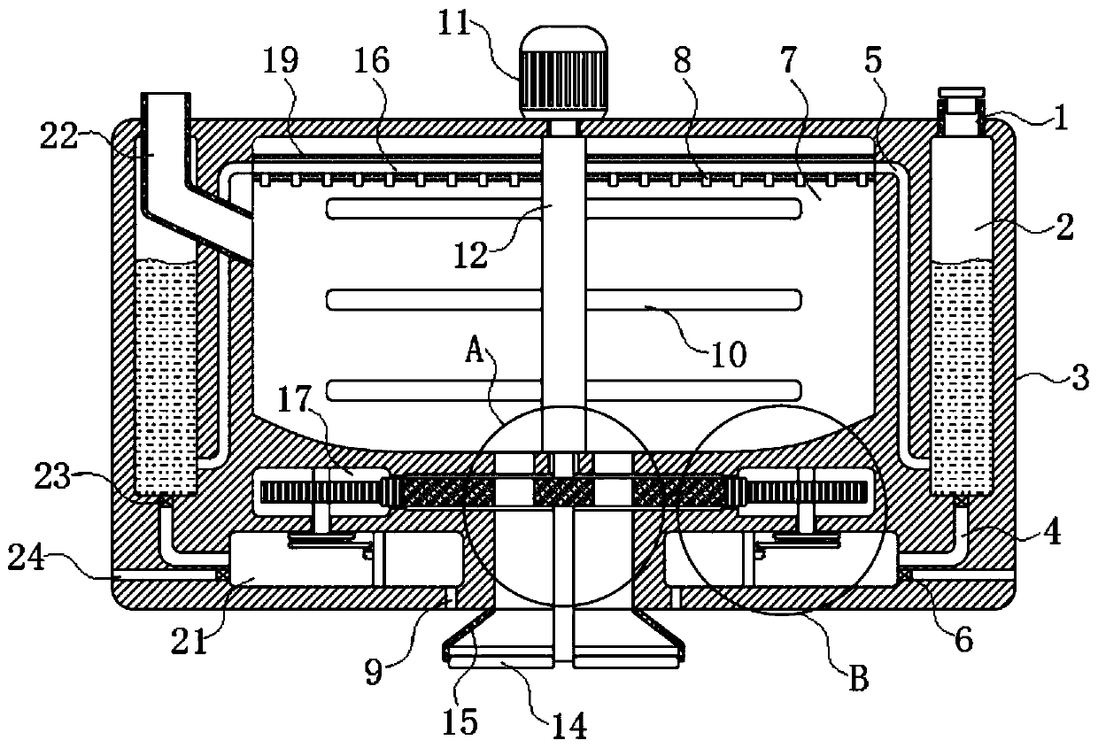
Figure 1 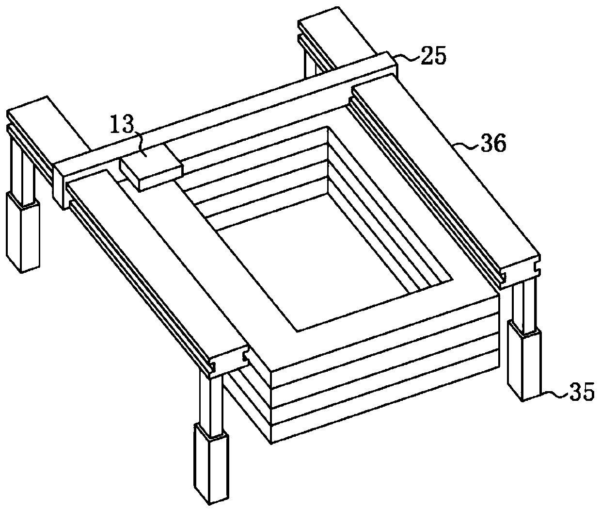
Figure 2 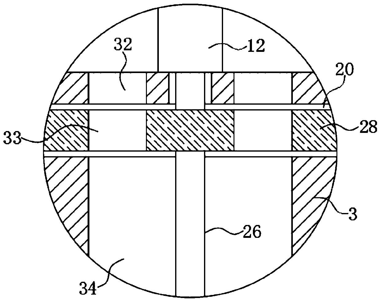
Figure 3
Abstract
Description
technical field
[0001] The invention relates to the technical field of building construction machinery and equipment, in particular to an automatic concrete pouring device for building construction. Background technique
[0002] At present, concrete pouring or wall laying in building construction is realized manually, but manual operation has problems such as workload, high work intensity and high labor cost, and manual pouring concrete or wall laying has problems such as long construction period and low efficiency.
[0003] In view of the above problems, the authorized patent document with the application number CN201310187282.6 discloses an automatic concrete pouring device for building construction, including a guide rail device and a crossbeam sliding along the guide rail device, the crossbeam is fixed with a steel bar insertion device and a concrete pouring bucket, A hot air blower device for drying concrete is also arranged beside the concrete pouring hopper.
[0004] ...
Examples
Embodiment 1
[0033] refer to Figure 1-6 , an automatic concrete pouring device for building construction, including two guide rails 36 fixed on the ground through two electric telescopic rods 35, a beam 25 sliding along the two guide rails 36, and a concrete pourer 13 slidingly connected to the beam 25 , a controller is installed on the guide rail 36, and a motion mechanism coupled with the controller is installed on the crossbeam 25 and the concrete pourer 13. The motion mechanism can be controlled by the controller to push the crossbeam 25 and the concrete pourer 13 to move. technology, so I won’t go into details here.
[0034]Concrete pourer 13 comprises pouring box 3, motor 11, stirring shaft 12 and a plurality of stirring blades 10, and motor 11 is fixedly connected on the upper end of pouring box 3, and stirring shaft 12 is fixedly connected on the end of motor 11 output shafts, and stirring shaft 12 Located in the pouring box 3, a plurality of stirring blades 10 are evenly distrib...
Embodiment 2
[0053] refer to Figure 7 , and embodiment 1 is different in that: ram board 31 changes vertical plate into L-shaped plate, air outlet 9 is changed into bar-shaped hole by circular hole, and the lower end of ram board 31 is fixedly connected with plasterboard 18, And the plasterboard 18 is slidably connected in the air outlet hole 9 .
[0054] It should be noted that, in order to ensure that the pouring nozzle 15 does not hinder the movement of the troweling board 18, the troweling board 18 is designed to be in the same shape as the side of the pouring nozzle 15. It is located at the center directly below the pouring nozzle 15, and two plasterboards 18 are attached to each other in this state.
[0055] The horizontal reciprocating movement of the ram board 31 can simultaneously drive two plastering boards 18 to horizontally reciprocate slide in the air outlet 9, thereby smoothing the concrete spread by the spreading board 14, which not only saves a lot of labor costs, but als...