
Self-climbing wind power maintenance crane
A crane and self-climbing technology, applied in the field of self-climbing wind power maintenance cranes, can solve the problems of self-adaptive arm structure and complex movements, slow expansion and contraction speed of oil cylinders, and limited effective lifting weight, etc., so as to improve maintenance efficiency and equipment Small size, easy disassembly and transition effect
Patent Information
- Authority / Receiving Office
- CN · China
- Patent Type
- Applications(China)
- Current Assignee / Owner
- Publication Date
- 2020-04-10
Smart Images
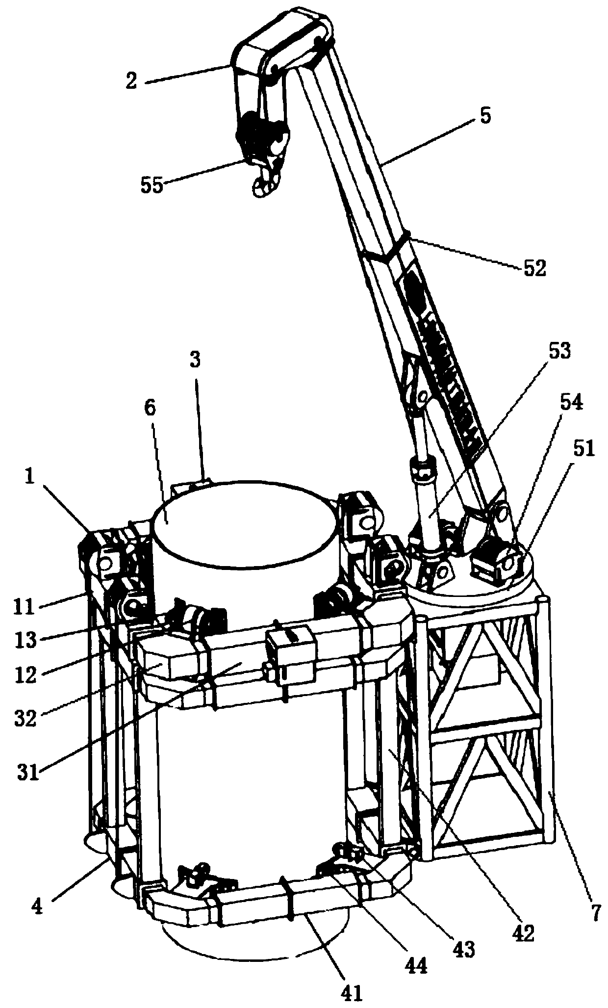
Figure 1 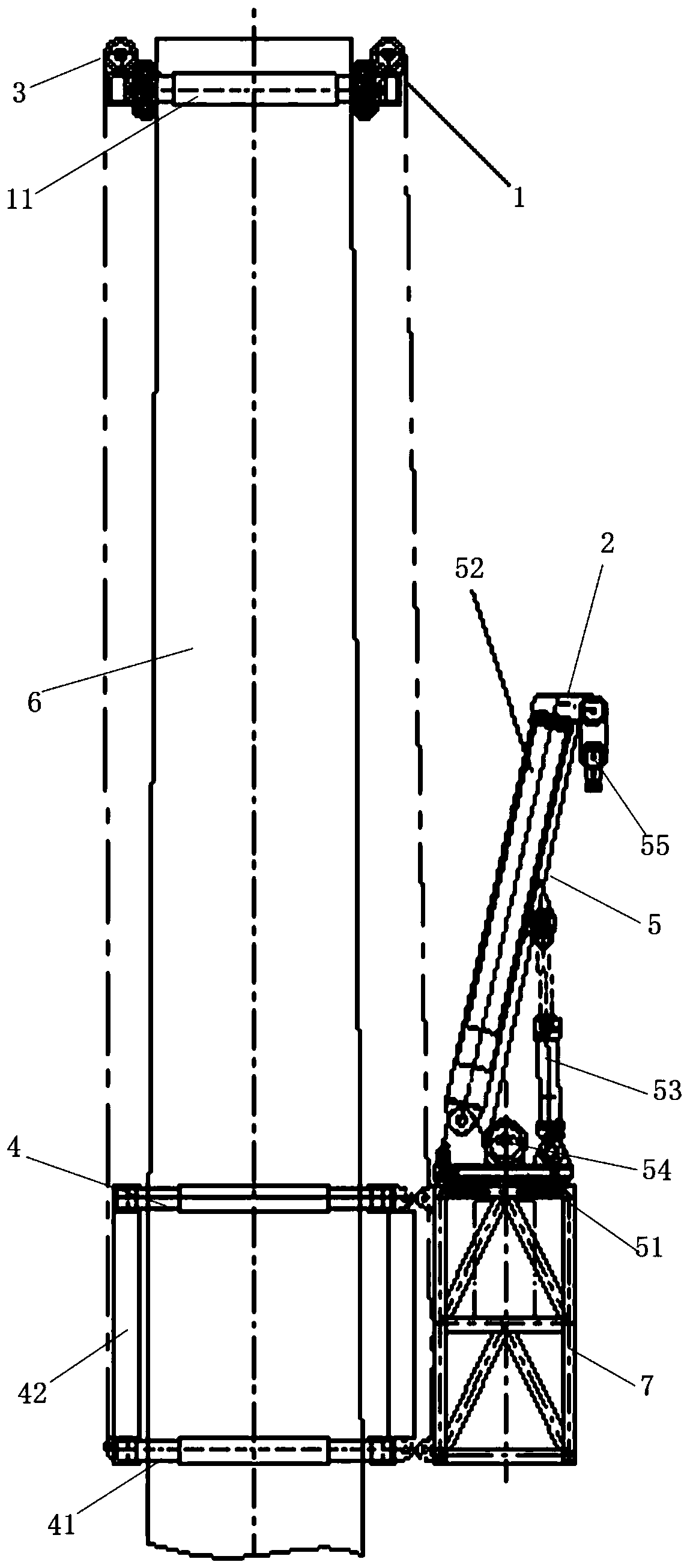
Figure 2 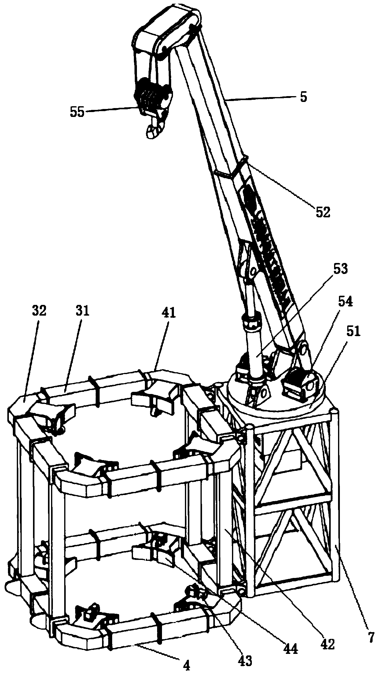
Figure 3
Abstract
Description
technical field
[0001] The invention relates to the technical field of lifting equipment, in particular to a self-climbing wind power maintenance crane. Background technique
[0002] Currently in the period of rapid growth of the wind power industry, wind power equipment is constantly developing in the direction of high power and high towers. Wind farms are mostly located in high mountains, Gobi, wilderness, offshore, shallow seas and other areas with inconvenient transportation and harsh environments, resulting in the demand for wind turbines. The equipment requirements for installation and maintenance are getting higher and higher, the operation difficulty is getting more and more difficult, and the lifting cost has also risen sharply.
[0003] The warranty period of wind turbines is generally 5 years. Almost all the fans installed during the explosive growth period have expired. The early design and manufacturing technology level is not high. After several years of operat...
Examples
no. 1 example
[0060] figure 1 It is a schematic diagram of the overall structure of a self-climbing wind power maintenance crane of the present invention, figure 2 It is a schematic diagram of the state of the self-climbing device traction lifting device in a self-climbing wind power maintenance crane of the present invention, and Fig. 3 is a structural schematic diagram of the lifting device in a self-climbing wind power maintenance crane of the present invention, Figure 4 It is a structural schematic diagram of the first embodiment of the first arm assembly and the second arm assembly in a self-climbing wind power maintenance crane of the present invention, Figure 5 It is a structural schematic diagram of the active wheel assembly in a self-climbing wind power maintenance crane of the present invention, Figure 6 It is a structural schematic diagram of a clamping assembly in a self-climbing wind power maintenance crane of the present invention, Figure 7 It is a structural schematic ...
Embodiment approach
[0070] In further embodiments of the present invention, please continue to refer to Figure 1 to Figure 7 As shown, the first arm assembly 11 and each second arm assembly 12 include: several telescopic arms 31 and several corner boxes 32, the several telescopic arms 31 and the several corner boxes 32 are arranged at intervals and connected in sequence to form a ring frame.
[0071] Preferably, the structures and principles of the first arm assembly 11 and the second arm assembly 41 are the same.
[0072] Preferably, the first arm assembly 11 and each second arm assembly 41 include: four telescopic arms 31 and a four-corner box 32, the four telescopic arms 31 and the four-corner boxes 32 are arranged at intervals and connected in sequence to form a square frame.
[0073] In a further embodiment of the present invention, each telescopic arm 31 includes: two first arms 311, two second arms 312 and two telescopic oil cylinders 313, and one end of the two first arms 311 is detachab...
no. 2 example
[0093] Figure 8 It is a structural schematic diagram of the second embodiment of the first arm assembly in a self-climbing wind power maintenance crane of the present invention, as shown in Figure 8 As shown, the main structure of the second embodiment is the same as that of the first embodiment, except that the first arm assembly 11 also includes: several guide rollers 17, two hydraulic reels 18 and at least two ropes 19, and several guide rollers 17 are all arranged on the outer wall of the first arm assembly 11, a number of guide rollers 17 are arranged at equal intervals along the outer circumference of the first arm assembly 11, two hydraulic rollers 18 are all arranged on the outer wall of the first arm assembly 11, two hydraulic Rollers 18 are all located between any two adjacent guide rollers 17, and each rope 19 is respectively connected with four guide rollers 17 and two hydraulic rollers 18 in transmission. Preferably, the hydraulic reel 18 is provided with a bra...