
Ball head type tripod universal joint with composite structure
A composite structure, three-ball pin technology, applied in the field of universal joints, can solve the problems of reduced function of the three-ball pin universal joint, limited service life of the ball-ring assembly, difficulty in manufacturing and assembly, etc. Strength and service life, the effect of reducing manufacturing difficulty and manufacturing cost
Patent Information
- Authority / Receiving Office
- CN · China
- Current Assignee / Owner
- Publication Date
- 2020-06-09
Smart Images
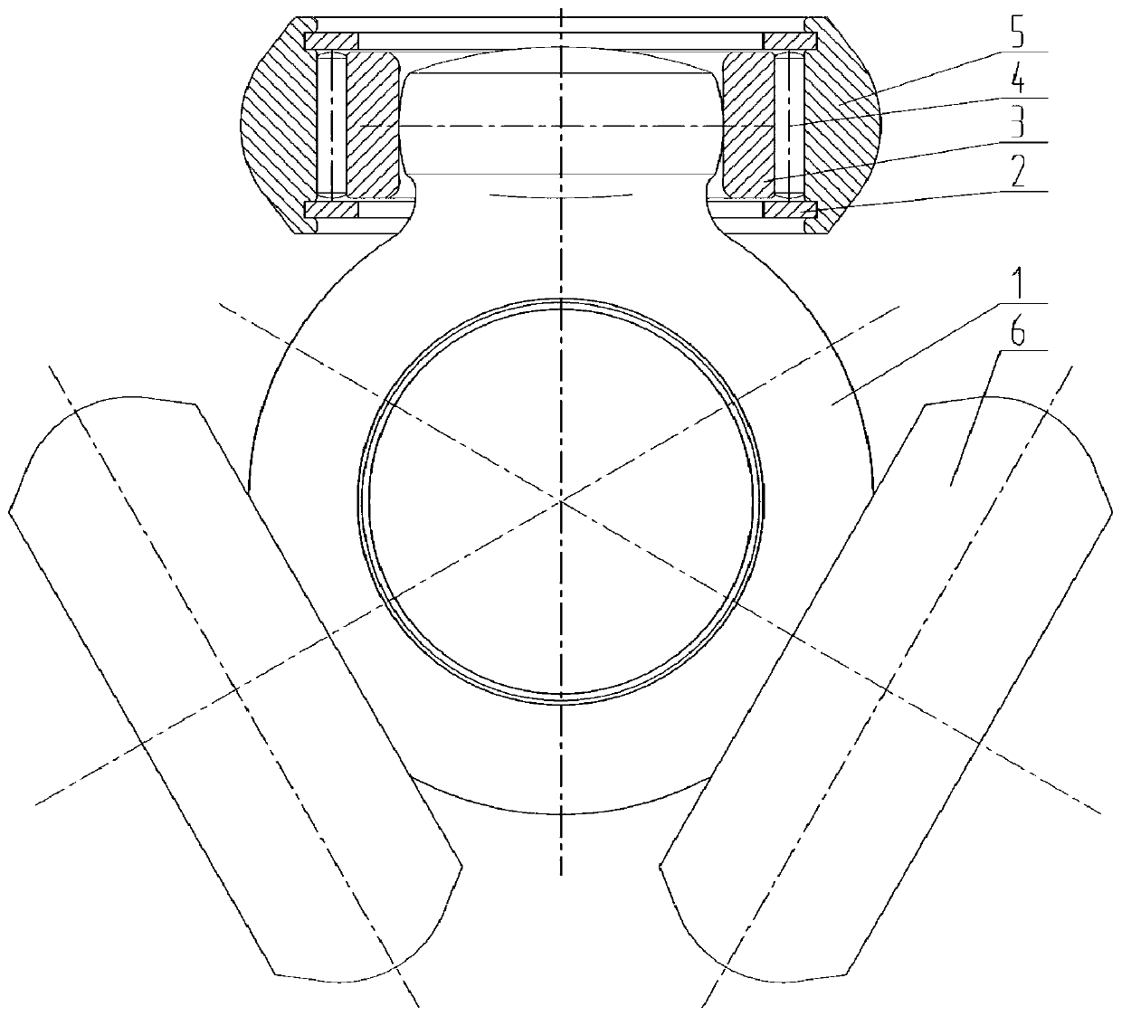
Figure 1 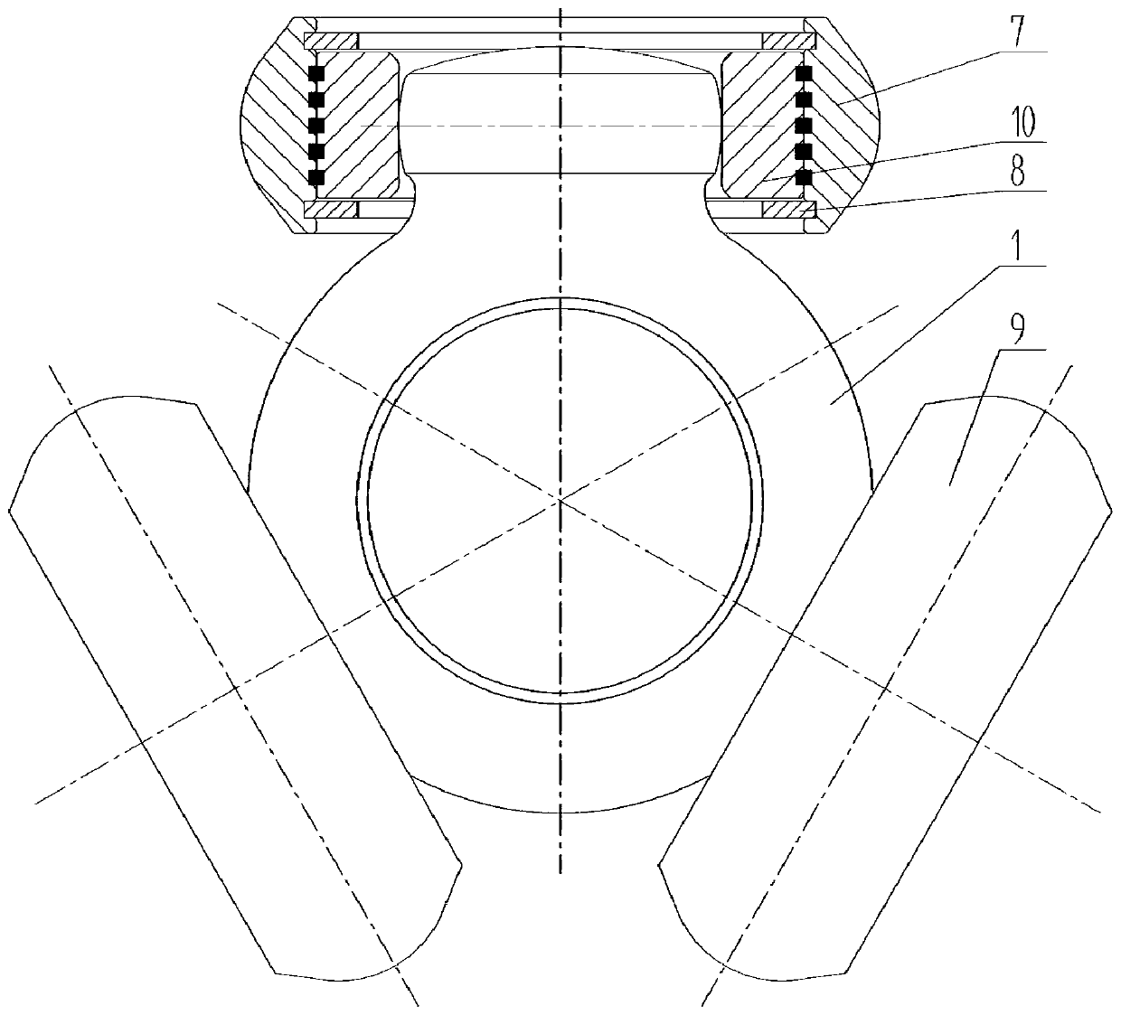
Figure 2 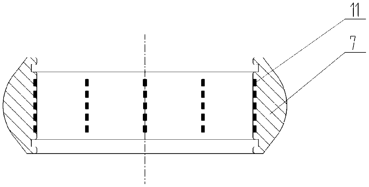
Figure 3
Abstract
Description
technical field
[0001] The invention relates to the field of universal joints, in particular to a ball-type tripod joint with a composite structure. Background technique
[0002] The constant velocity universal joint is a device that connects two shafts with an angle between the shafts or changes in mutual position, and makes the two shafts transmit power at the same angular velocity. speed problem. Ball-type tripods are commonly used because they work well at larger swing angles. The main structure of the ball-type tripod joint of the prior art is as attached Figure 1 As shown, it mainly includes: tripod frame 1, needle retaining ring 2, original inner ring 3, needle roller 4, original outer ring 5, small bearing assembly 6, in order to ensure that the tripod will not fall off during assembly and work If the needle does not get stuck, it is necessary to use the needle retaining ring 2 and apply an appropriate amount of grease between the original outer ring 5, needle rol...
Examples
Embodiment 1
[0016] Embodiment 1: as attached figure 2 As shown, the ball-type three-pin universal joint of this composite structure mainly includes a tripod frame 1, an inner ring 10, an outer ring 7, a retaining ring 8, a bearing 9, and three journals of the tripod frame 1 Install the bearing 9, the inner ring 10 of the bearing 9 is fitted on the journal of the three-pin frame 1, the outer diameter of the inner ring 10 is matched with the outer ring 7, the outer diameter of the inner ring 10 is in contact with the inner diameter of the outer ring 7 to achieve circumferential fixation, the inner The two ends of the ring 10 are axially positioned through the retaining ring 8 fixed on the outer ring 7 . A groove A11 and a groove B12 are respectively designed on the inner hole wall of the outer ring 7 and the outer hole wall of the inner ring 10 . Groove 11 and groove B12 can also be circular holes. The number and size of the slots 11 and B12 are determined according to specific working c...
Embodiment 2
[0018] Embodiment 2: as attached Figure 5 As shown, on the basis of Embodiment 1, only the inner hole wall of the outer ring 7 is designed with a groove A11. There is no groove B12 on the outer hole wall of the inner ring 10 .
Embodiment 3
[0019] Embodiment 3: as attached Image 6 As shown, on the basis of embodiment 1, only the outer hole wall of 10 is designed with groove B12. There is no groove A11 on the inner ring of the inner hole wall of the outer ring 7 .