
Efficient wallboard forming machine
A molding machine and wall panel technology, which is applied in the direction of ceramic molding machines, auxiliary molding equipment, mold fixing devices, etc., can solve the problems of end face template installation position deviation, unqualified, ball falling off, etc.
Patent Information
- Authority / Receiving Office
- CN · China
- Current Assignee / Owner
- Publication Date
- 2020-06-19
Smart Images
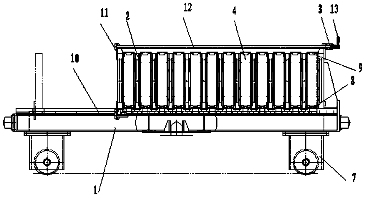
Figure 1 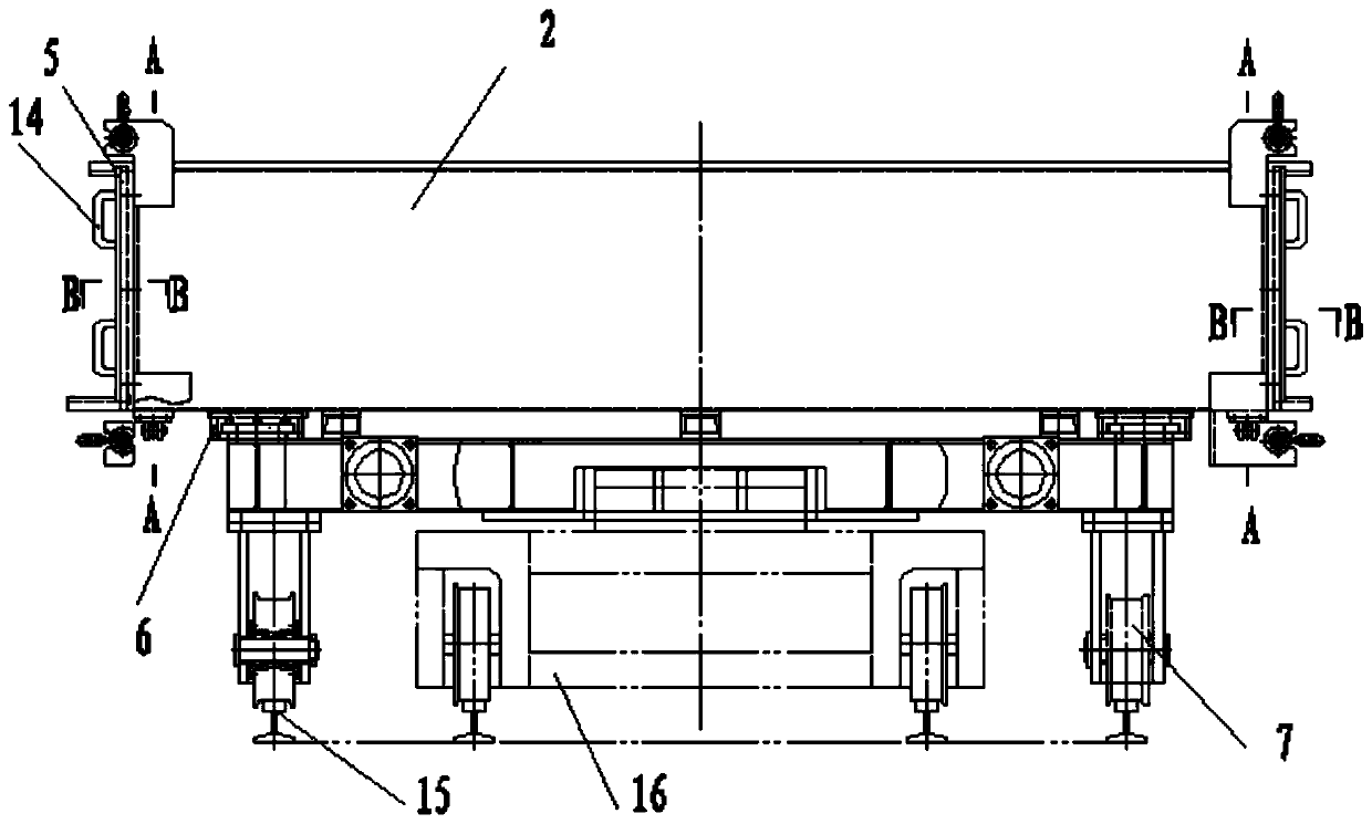
Figure 2 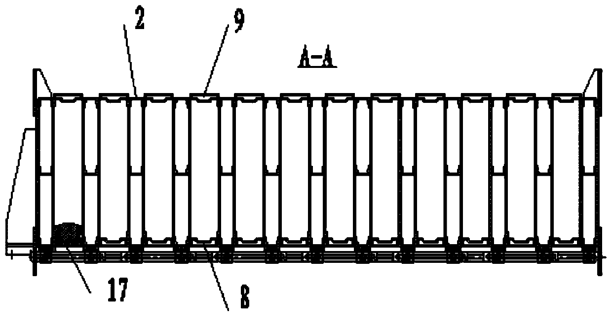
Figure 3
Abstract
Description
technical field
[0001] The invention relates to the technical field of wallboard forming machine production, in particular to a high-efficiency wallboard forming machine. Background technique
[0002] With the country's vigorous promotion of prefabricated buildings, various new types of prefabricated panels have emerged. These prefabricated new panels are poured and formed by a mold forming machine, that is, specific lightweight cement slurry is poured into the mold cavity of the forming machine, and cured and formed after curing.
[0003] Existing wall panel molding machines are mainly aimed at hollow panels or solid foamed cement panels, and there is no mold molding machine for composite panels with a sandwich layer and glass fiber grid cloth.
[0004] The disadvantages of the existing wall panel forming machine are:
[0005] 1. There is no positioning and fixing device for the glass fiber mesh. When pouring, the glass fiber mesh needs to be tightened manually, which not...
Examples
Embodiment Construction
[0025] A high-efficiency wallboard molding machine, which includes a frame 1, a plurality of templates 2, a plurality of end templates 4 and a plug-in plate 5, two template guide rails 10 are fixedly installed on the frame along the extension direction, and the template at the left end is fixed Installed on the frame, the inner and outer sides of the bottom of the remaining templates are respectively clamped on the template guide rails through the slider 6, and a lower mold strip 8 is vertically placed above the template guide rails between each two templates. The sides are snapped into the end formwork and fixed by the first positioning pin 17, and the top of the end formwork is snapped onto the upper mold bar 9. There are pin holes corresponding to each other between the formwork and the end formwork, and the pin holes are inserted with the first Two positioning pins 18, the inner and outer sides of the template are respectively provided with slots 19 near the left and right ...