
Mountain river wharf structure
A technology for rivers and mountainous areas, applied in the field of river wharf structures in mountainous areas, can solve problems such as no requirements for flood control and flood season, and achieve the effects of solving settlement deformation, rapid water level changes, and reasonable stress
Patent Information
- Authority / Receiving Office
- CN · China
- Patent Type
- Applications(China)
- Current Assignee / Owner
- Publication Date
- 2020-07-17
Smart Images
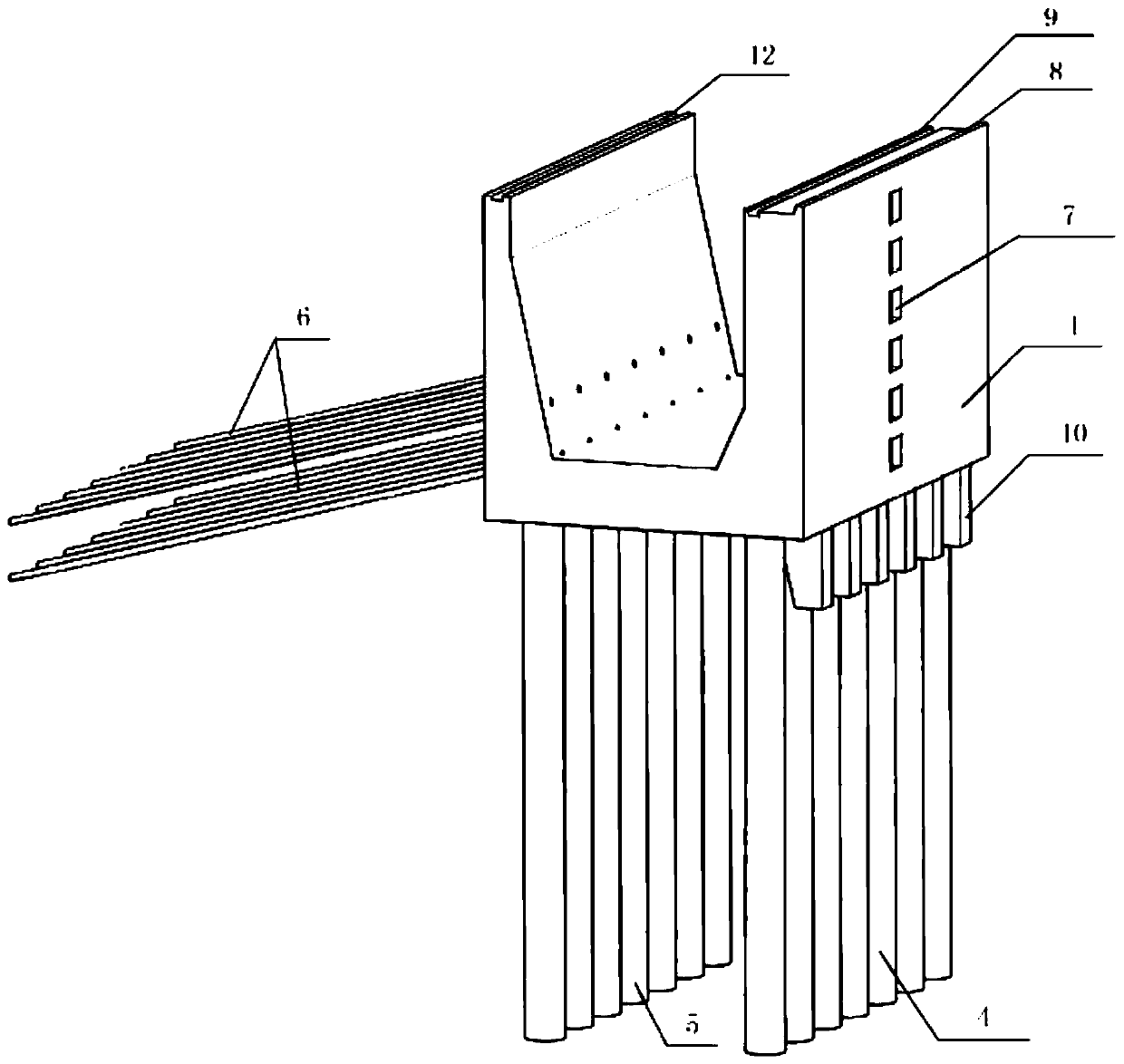
Figure 1 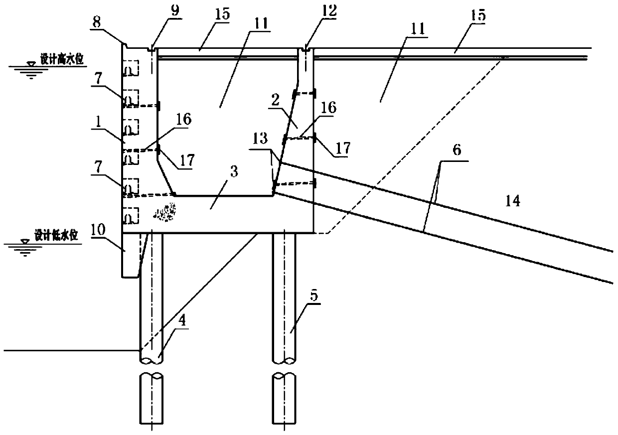
Figure 2
Abstract
Description
technical field
[0001] The invention relates to the technical field of water transport engineering, in particular to a wharf structure for mountainous rivers. Background technique
[0002] The wharf is a building for ships to berth, moor and load and unload cargo. Its structure types include gravity type, sheet pile type, high pile type, slope type and floating type. With the canalization of China's inland rivers and the improvement of waterway grades, specialized wharfs are gradually developing towards the middle and upper reaches of inland rivers and mountainous waterways. Compared with waterways in coastal and plain areas, mountainous waterways have the characteristics of steep bank slopes, large water depths, large water level differences, and rapid water level changes.
[0003] The gravity wharf relies on its own gravity to resist sliding and overturning caused by the earth pressure behind the wall, and is suitable for foundations with better foundation bearing capacit...
Examples
Embodiment Construction
[0036] The present invention will be described in further detail below in conjunction with the accompanying drawings and specific embodiments.
[0037] like figure 1 and figure 2 As shown, the wharf structure of the mountainous river in this embodiment includes two groups of row piles arranged in parallel along the upstream and downstream directions of the mountainous river and a U-shaped structure arranged on the top of the row of piles; Wall 1, rear wall 2, two groups of walls and the cap 3 connecting the top of the row of piles and the bottom of the wall; the top of the U-shaped structure is covered with a surface layer 15; the top of the wall is also provided with a track, and the top of the front wall 1 is provided with a The front track 9 and the top of the back wall 2 are provided with a back track 12 .
[0038] In this embodiment, the U-shaped structure and the surface layer 15 enclose a hollow cavity filled with fillers.
[0039] In this embodiment, the filler is ...