
Restoration assistor for shoulder joint
An auxiliary device, shoulder joint technology, applied in medical science, fractures, etc., can solve the problem of low success rate, and achieve the effect of humanized force angle, high bearing capacity and force application.
Patent Information
- Authority / Receiving Office
- CN · China
- Patent Type
- Applications(China)
- Current Assignee / Owner
- Publication Date
- 2020-08-14
Smart Images
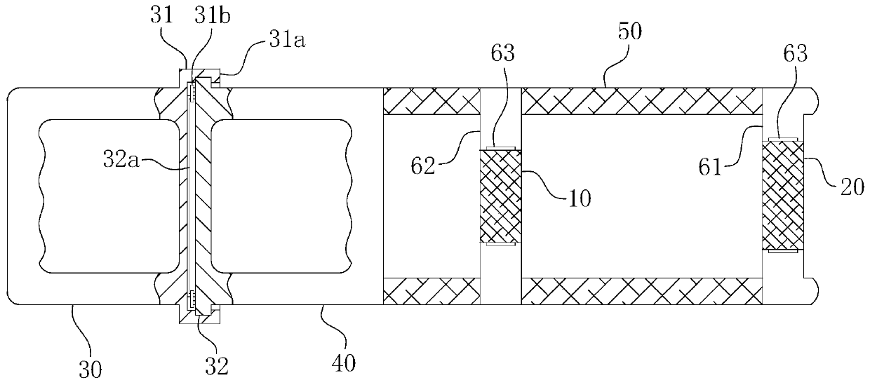
Figure 1 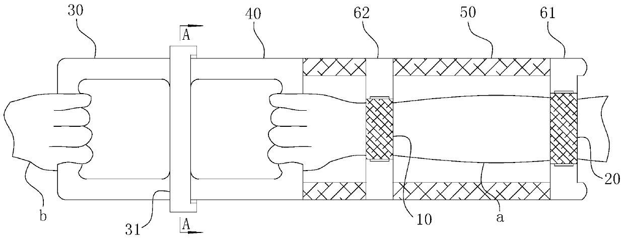
Figure 2 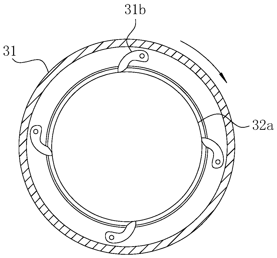
Figure 3
Abstract
Description
technical field
[0001] The invention belongs to the field of shoulder joint reduction aids, in particular to a shoulder joint reduction aid. Background technique
[0002] Joint dislocation, also known as dislocation, refers to the loss of the normal position of the upper and lower bone ends that make up the joint, and a dislocation phenomenon has occurred. Among the cases of joint dislocation, shoulder joint dislocation is the most common, accounting for about 50% of the whole body joint dislocation, which is related to the anatomical and physiological characteristics of the shoulder joint, such as large humeral head, shallow and small glenoid, loose joint capsule, anterior and inferior tissue Weakness, large range of joint motion, and even more chances of being subjected to external forces. Shoulder dislocations mostly occur in young adults, men, and are often caused by violence. The clinical manifestations of shoulder dislocation include severe pain at the shoulder joint...
Examples
Embodiment Construction
[0034] For ease of understanding, the attached Figure 1-5 Shown specific embodiment, concrete structure of the present invention and mode of operation are further described as follows:
[0035] Specific embodiments of the present invention refer to Figure 1-5 As shown, it is the ratchet pawl cooperation structure of the first circular plate 31 and the second circular plate 32, and its main components include the first handle 30, the first circular plate 31, the second circular plate 32, the second handle 40, the fixed part, the boom base plate 61, the boom restraint band 20, the forearm base plate 62 and the forearm restraint band 10. in:
[0036] The first handle 30, the first circular plate 31, the second circular plate 32 and the second handle 40 together constitute the front end structure of the present invention, and its specific matching method refers to Figure 3-4 shown. During actual assembly, the first handle 30 and the second handle 40 are in the shape of a "U...