
Energy-saving and environment-friendly high-energy screw press
A screw press, energy saving and environmental protection technology, applied in the direction of presses, punching machines, manufacturing tools, etc., can solve the problems of only transmission efficiency, large acceleration mass, large energy consumption, etc., achieving low transmission power, large total inertia, saving energy The effect of power
Patent Information
- Authority / Receiving Office
- CN · China
- Patent Type
- Applications(China)
- Current Assignee / Owner
- Publication Date
- 2020-10-09
- Estimated Expiration
- Not applicable · inactive patent
Smart Images
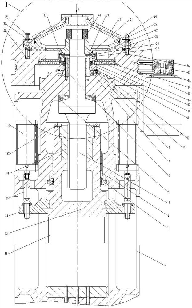
Figure 1 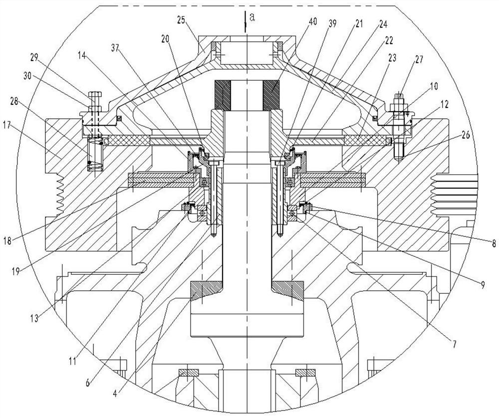
Figure 2
Abstract
Description
technical field
[0001] The invention relates to an energy-saving and environment-friendly high-energy screw press, which can be widely used in the pressure forming process of forgings. Background technique
[0002] In the traditional screw press, the screw and the driven pulley flywheel are always connected together. When the slider goes down, the driven pulley flywheel and the screw are accelerated together, and they are reversed together when turning, so the accelerated mass is relatively large. , travel is limited. Moreover, since the rotating mass of the driven pulley type flywheel and the screw rod will be accelerated twice from a static state every time a stroke is performed, the energy consumption is large. The friction loss between the driven pulley flywheel and the friction clutch disc can account for 60% of the output power of the motor, so that its transmission efficiency is only 10% to 15%. Contents of the invention
[0003] The purpose of the present inventi...
Examples
Embodiment Construction
[0022] exist figure 1 , figure 2Among them, the energy-saving and environment-friendly high-energy screw press of the present invention includes a fuselage 1 provided with an X-shaped guide rail 38, and a circular guide rail 2 fixedly installed on the inner hole of the fuselage through interference fit for blocking the circular guide rail and installing The circular guide rail cover 3 on the fuselage, the spherical bearing seat 4 installed on the fuselage beam, the screw rod 5 passing through the fuselage beam hole, having a spherical surface and matching contact with the spherical bearing seat, passing through the screw rod and passing through Fastening bolts 39 are installed on the stepped ring bearing on the top surface of the fuselage beam to fix the inner body 6, pass through the stepped ring bearing to fix the inner body and install the thrust ball bearing 7 on the top surface of the fuselage beam, and are located in the thrust ball bearing The convex block cover 8 ins...