
Mechanical shutter for vacuum environment
A mechanical shutter, vacuum environment technology, applied in the field of photography, can solve the problems of exposure errors, difficulty in meeting size requirements, and complicated operations, and achieve the effects of wide application, protection and simple operation.
Patent Information
- Authority / Receiving Office
- CN · China
- Patent Type
- Applications(China)
- Current Assignee / Owner
- Publication Date
- 2020-11-03
Smart Images
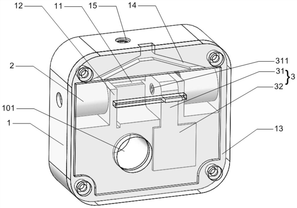
Figure 1 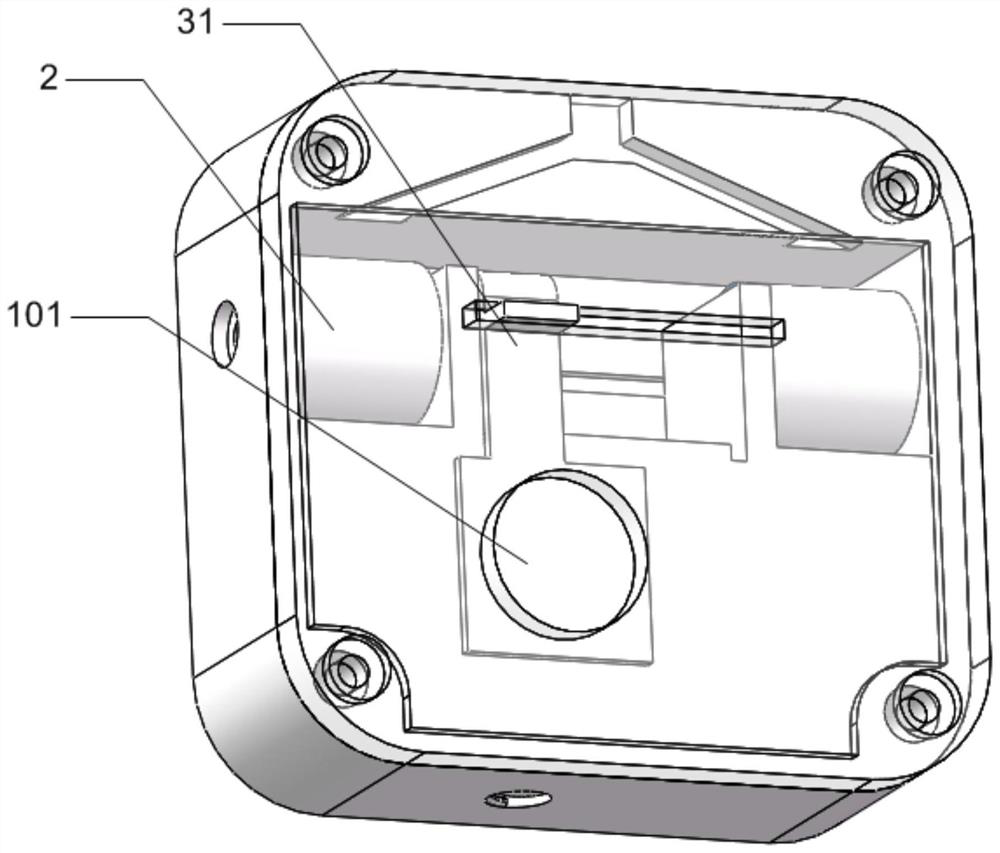
Figure 2 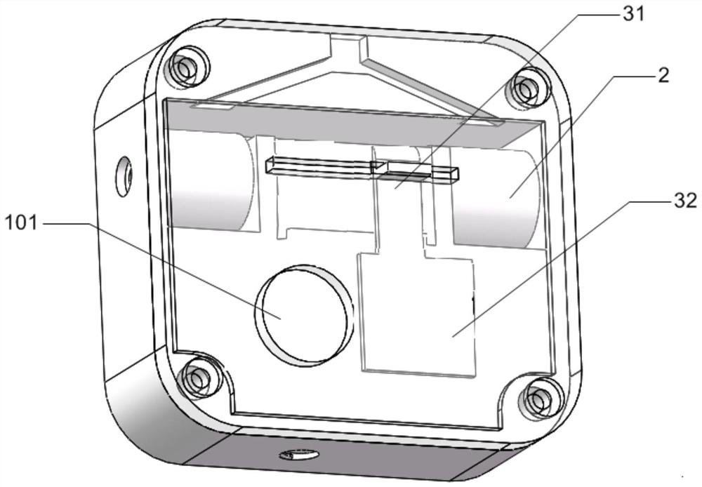
Figure 3
Abstract
Description
technical field
[0001] The invention relates to a mechanical shutter, in particular to a mechanical shutter used in a high-vacuum environment, and belongs to the field of imaging. Background technique
[0002] In some optical experiments, it is necessary to use the camera to collect the imaging information of light to obtain experimental data. The mechanical shutter is a key device to control the exposure time of the camera, which has a direct impact on the imaging quality of the camera.
[0003] The optical experiment environment is different from the conventional camera environment. In addition to the extremely high requirements for shutter response time and action time, in optical experiments using high-energy lasers, the laser can reach TW or even PW levels. Under such high-energy lasers, the camera Directly receiving high-energy laser signals will cause damage to it. In order to avoid "accidental damage" to the camera by high-energy laser, it is necessary to use a mecha...
Examples
Embodiment Construction
[0048] The present invention will be described in further detail below by means of the accompanying drawings. Through these descriptions, the features and advantages of the present invention will become more apparent.
[0049] The present invention provides a kind of mechanical shutter that is used for optical experiment of high vacuum environment, comprises shutter base 1, is provided with light through hole 101 on shutter base 1, as figure 1 shown.
[0050] The light hole 101 passes through the shutter base 1 , and the electromagnet 2 and the light shielding part 3 are arranged in the shutter base 1 , and the permanent magnet 311 is arranged on the light shielding part 3 .
[0051] In the present invention, the light-shielding part 3 is driven electromagnetically instead of the traditional motor drive, which solves the problem that the motor lubricating grease volatilizes in a vacuum and affects the experimental results and contaminates the optical devices.
[0052] The li...