
Auxiliary assembly equipment for aircraft nose landing gear strut
A technology for nose landing gear and auxiliary assembly, applied in aircraft assembly and other directions, can solve the problems of high risk, increased aircraft total weight, long time consumption, etc., and achieve the effects of reducing safety risks, reducing operators, and easy operation.
Patent Information
- Authority / Receiving Office
- CN · China
- Current Assignee / Owner
- Publication Date
- 2020-11-06
- Estimated Expiration
- Not applicable · inactive patent
Smart Images
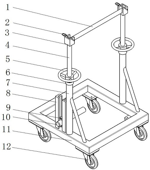
Figure 1 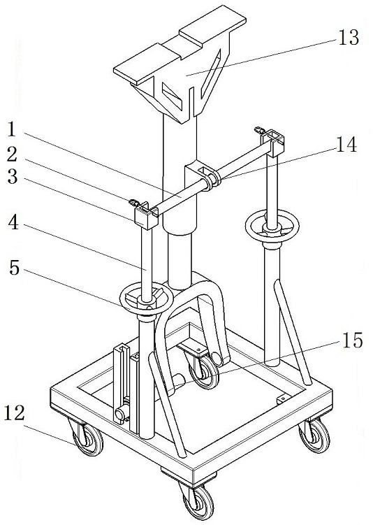
Figure 2
Abstract
Description
technical field
[0001] The invention belongs to the field of aircraft assembly tool design, and in particular relates to an auxiliary assembly equipment for aircraft front landing gear pillars. Background technique
[0002] In the past, due to the low flying speed of the aircraft, the requirements for the aerodynamic shape of the aircraft were not very strict, so the landing gear of the aircraft was composed of fixed brackets and wheels, which did not require high technology for manufacturing. When the plane is in the air, the landing gear remains exposed outside the fuselage. As the flight speed of the aircraft continues to increase, the aircraft quickly crosses the barrier of sound speed. Since the flight resistance increases sharply with the increase of the flight speed, the exposed landing gear seriously affects the aerodynamic performance of the aircraft. hindered the further improvement of flight speed.
[0003] Therefore, people have designed a retractable landing g...
Examples
Embodiment 1
[0034] An aircraft nose landing gear pillar auxiliary assembly equipment, such as figure 1 As shown, it is connected with the front landing gear strut 13, and is used for the equipment of the front landing gear strut 13, including the base structure, the lifting structure installed on the base structure, and the support structure installed on the lifting structure for supporting the front landing gear strut 13 ; The support structure is connected to the front landing gear strut 13;
[0035] The lifting structure includes brackets installed on the left and right sides of the base structure, and the bracket includes a pillar 7 installed on the base structure, a sleeve assembly 6 installed on the top of the pillar 7, and a socket assembly 6 that passes through the sleeve assembly 6 and connects upward to the support structure. The screw mandrel 4 ; the sleeve assembly 6 is provided with a turntable 5 for controlling the degree of threading of the screw mandrel 4 through the sleev...
Embodiment 2
[0038] The present invention is on the basis of above-mentioned embodiment 1, in order to realize the present invention better, further, as figure 1 , figure 2 As shown, the support structure includes a support rod 1, a quick release pin 2, a bracket 3, and an outer cylinder bushing 14;
[0039] The two brackets 3 are installed on the tops of the left and right screw rods 4, the two ends of the support rod 1 are respectively installed on the left and right brackets 3, and the two quick release pins 2 pass through the brackets 3 respectively. It is connected with both ends of the support rod 1, and is used for fixing and axially limiting the support rod;
[0040] The outer cylinder bushing 14 is installed on the upper part of the front landing gear strut 13 , and the support rod 1 passes through the outer cylinder bushing 14 and is connected with the front landing gear strut 13 .
[0041] Working principle: Tingge quick release pin 2 fixes the support rod 1 while also axiall...
Embodiment 3
[0044]The present invention is based on any one of the foregoing embodiments 1-2, in order to better realize the present invention, further, as figure 1 , figure 2 As shown, the lifting structure also includes guide rails 8, bearings 9, positioning pins 10, piston rod bushings 15;
[0045] The guide rail 8 is installed on the base structure and connected in parallel with the pillar 7; the bearing 9 is arranged on the guide rail 8;
[0046] The piston rod bushing 15 is installed at the bottom of the front landing gear pillar 13; one end of the positioning pin 10 is movably connected with the guide rail 8 through the bearing 9, and the other end is connected with the front landing gear pillar 13 through the piston rod bushing 15.
[0047] In order to better realize the present invention, further, the lifting structure further includes a guide rail 8, a bearing 9, a positioning pin 10, and a piston rod bushing 15;
[0048] The guide rail 8 is installed on the base structure an...