
A trolley line that can provide power supply for rotary rail change
A trolley line and rotating guide rail technology, applied in the field of trolley line, can solve problems such as the inability to meet the simultaneous operation of multiple cages, and achieve the effects of high work efficiency, improved conveying efficiency, and stable operation
Patent Information
- Authority / Receiving Office
- CN · China
- Patent Type
- Patents(China)
- Current Assignee / Owner
- Publication Date
- 2022-05-24
Smart Images
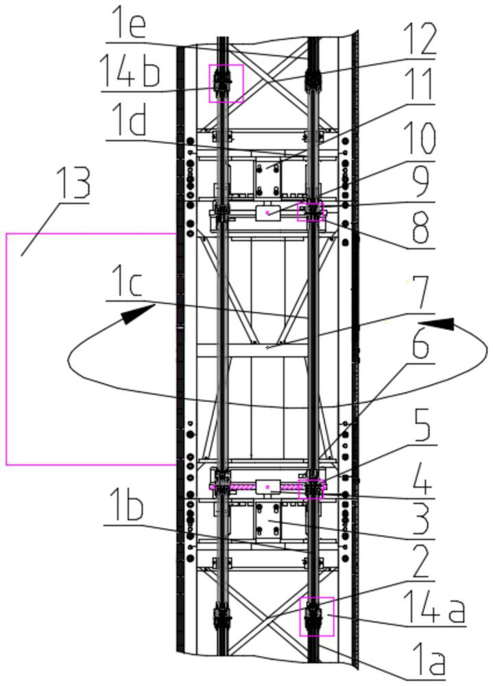
Figure 1 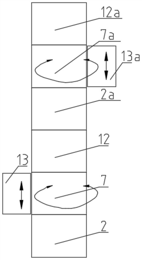
Figure 2 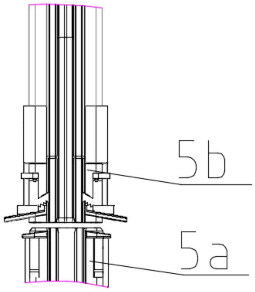
Figure 3
Abstract
Description
technical field
[0001] The invention relates to the technical field of trolley wire devices for construction elevators, in particular to a trolley wire that can provide power supply for rotating rails. Background technique
[0002] The existing construction hoists are mainly used for straight up and down in the vertical direction, and they are both left and right double-cage configuration structures, which require multiple reciprocating loading and unloading of goods in transportation operations, and the loading and unloading efficiency of goods is low. To this end, Chinese patent CN 201510124152.7 proposes a rotating rail changing device, including a fixed frame body, a rotating frame body and a track, the relative rotation of the fixed frame body and the rotating frame body is realized by using a slewing bearing, and is locked or locked by a rotary locking device. Release the rotational frame body degrees of freedom. The invention solves the problem that the existing rack...
Examples
Embodiment Construction
[0042] In order to describe the technical content, structural features, achieved objects and effects of the technical solution in detail, the following detailed description is given in conjunction with the specific embodiments and the accompanying drawings.
[0043] see figure 1 , this embodiment provides a trolley line that can provide power supply for rotating rails, the trolley line is multi-strand in use and is installed symmetrically at 180 degrees relative to the rotation center. Each trolley line is a multi-segment structure, and is specifically composed of a first power supply point trolley line 1a, a lower end trolley line 1b of the rotary joint, a lower fixed section 14a, a lower end trolley line roller 6, and a slewing joint power supply trolley line. 1c, the first lower transition rotary joint 5, the upper end sliding contact line 1d of the rotary joint, the upper end sliding contact line roller 9, the first upper transition rotary joint 8, the upper fixed joint 14...