
MPPT tracking method for inverter, storage medium and computing equipment
A technology of computing equipment and inverters, applied in the direction of instruments, adjusting electric variables, control/regulation systems, etc., can solve problems such as slow dynamic response speed, DC side undervoltage, slow power tracking speed, etc., to achieve simple engineering implementation, The algorithm logic is clear and easy to promote and apply
Patent Information
- Authority / Receiving Office
- CN · China
- Patent Type
- Applications(China)
- Current Assignee / Owner
- Publication Date
- 2021-01-22
- Estimated Expiration
- Not applicable · inactive patent
Smart Images
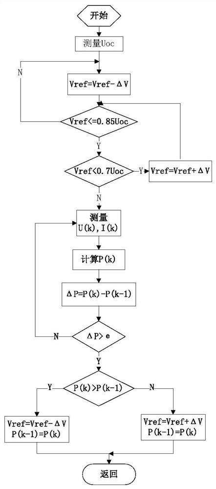
Figure 1 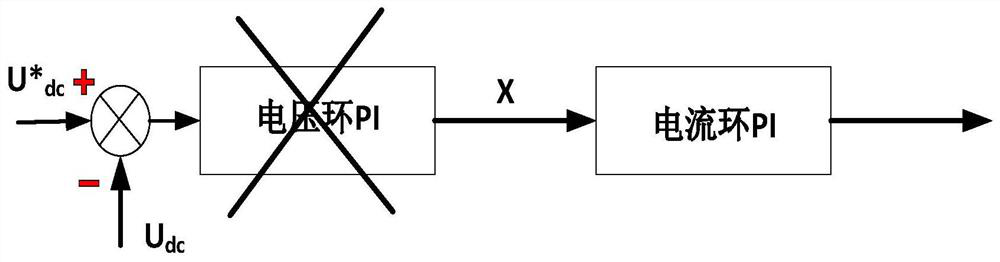
Figure 2
Abstract
Description
technical field
[0001] The invention belongs to the technical field of inverter control, and in particular relates to an MPPT tracking method for an inverter, a storage medium and a computing device. Background technique
[0002] MPPT (Maximum Power Point Tracking) tracking technology is to track and control the changes in output voltage and current caused by changes in solar cell surface temperature and solar irradiance, so that the array can always be kept in the working state of maximum output. The adjustment behavior to obtain the maximum power output is called maximum power point tracking (MPPT tracking technology). Because solar cells are affected by external factors such as light intensity and the environment, their output power changes, and the light intensity generates more electricity. The inverter with MPPT maximum power tracking is to make full use of solar cells and make them run at the maximum power point. That is to say, under the condition of constant solar...
Examples
Embodiment Construction
[0029] see figure 1 , a MPPT tracking method for an inverter of the present invention, the photovoltaic cell panel has the characteristics that the open circuit voltage Uoc of the photovoltaic cell panel varies within 30V during normal operation in one day, and the maximum power point is 0.78~0.8Uoc; the specific steps are as follows:
[0030] S1. Power on the inverter, detect the current open circuit voltage value Uoc, and start the grid-connected operation of the inverter;
[0031] When the DC bus voltage Vref is greater than 0.85Uoc, the PI control loop of the voltage outer loop is disconnected, and the given value X of the current loop is directly controlled. The given value X starts to increase rapidly from 0, and increases △X every interrupt cycle (each interrupt The period is only 333us), at this time the power rises rapidly, and the DC bus voltage Vref rapidly decreases to near the maximum power point voltage.
[0032] S2. When the DC bus voltage Vref is reduced below...