
Clamping device for diesel engine rocker arm support drill clamp
A technology of rocker arm support and clamping device, which is applied in the direction of drilling molds for workpieces, etc., can solve the problems of reduced machining accuracy of parts, increased cost of fixtures, and increased times of clamping by operators, so as to ensure positioning accuracy and solve problems. The effect of compressing the flat position
Patent Information
- Authority / Receiving Office
- CN · China
- Patent Type
- Applications(China)
- Current Assignee / Owner
- Publication Date
- 2021-07-23
Smart Images
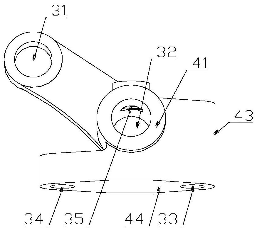
Figure 1 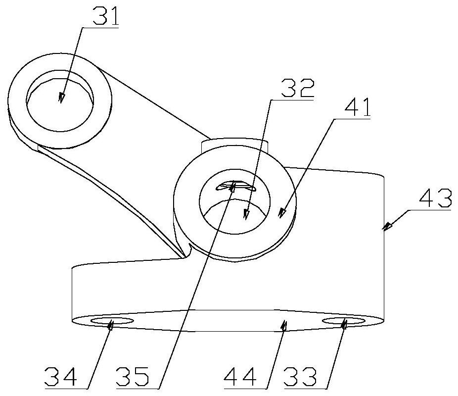
Figure 2 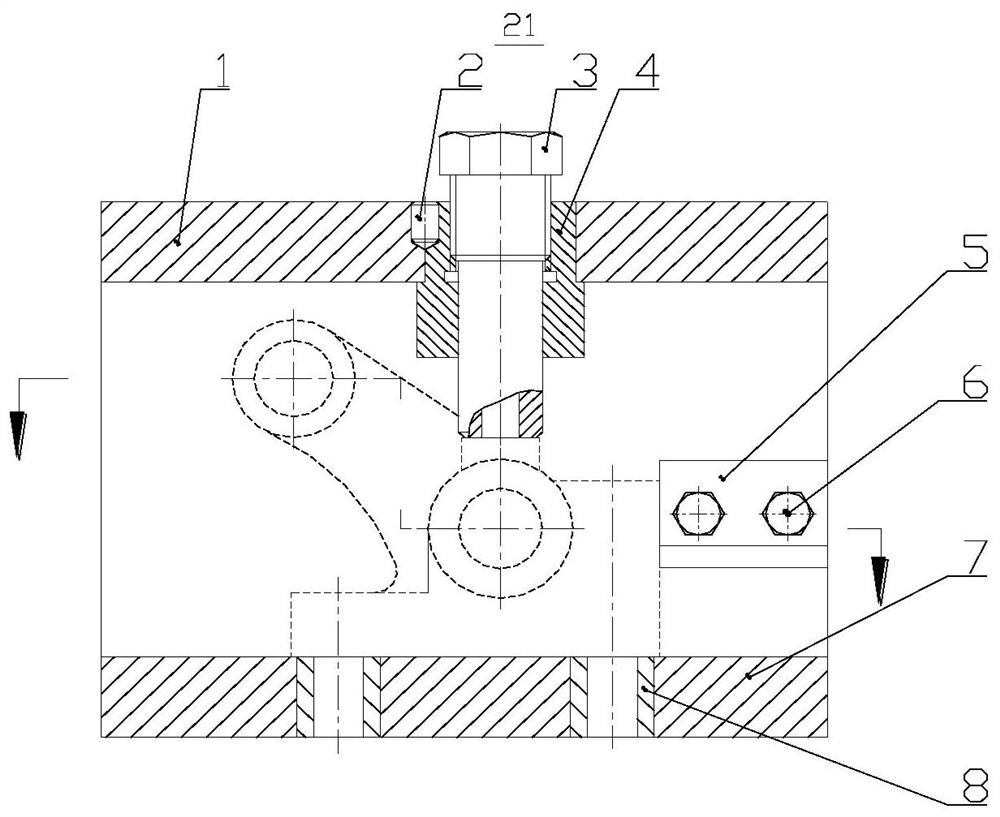
Figure 3
Abstract
Description
technical field
[0001] The invention relates to a clamping device of a clamp, in particular to a clamping device of a diesel engine rocker arm support drill clamping device, which belongs to the technical field of mechanical manufacturing technology of diesel engine parts. Background technique
[0002] Diesel engine rocker arm supports are generally castings, such as figure 1 , figure 2 As shown, compared with general machined parts, this part is small in size and complex in shape; holes are provided in the up, down, front and back directions of the part, and multiple facets with different heights are set in the same direction, and each facet is set There is one hole. Therefore, in order to improve the machining accuracy of the part and improve the machining efficiency, after the part is milled, a drilling jig is used to process the holes on the part.
[0003] Due to the small parts, there are many holes to be processed with high precision, such as: rocker shaft support h...
Examples
Embodiment Construction
[0031] In order to make the purpose and technical solutions of the present invention clearer, the present invention will be further described below in conjunction with accompanying drawing and embodiment:
[0032] Those skilled in the art can understand that, unless otherwise defined, all terms (including technical and scientific terms) used herein have the same meaning as commonly understood by one of ordinary skill in the art to which this invention belongs.
[0033] The meaning of "left, right, up, down, front, back" mentioned in the present invention means that when the reader is facing the drawings, the left side of the reader is left, the right side of the reader is right, and the reader's right side is right. The upper edge of the reader is the upper edge, the lower edge of the reader is the lower edge, the face in the paper in front of the reader is the front, and the face facing the reader is the back, rather than specific limitations to the present invention. The fix...