
Movable support for spraying and curing bolt connection friction test plate and manufacturing method thereof
A manufacturing method and mobile technology, applied in the direction of spraying device, etc., can solve the problem of not being able to spray the test plate with bolt friction, and achieve the effect of ensuring anti-slip performance, reducing spraying difficulty and improving spraying efficiency.
Patent Information
- Authority / Receiving Office
- CN · China
- Patent Type
- Applications(China)
- Current Assignee / Owner
- Publication Date
- 2021-09-07
Smart Images
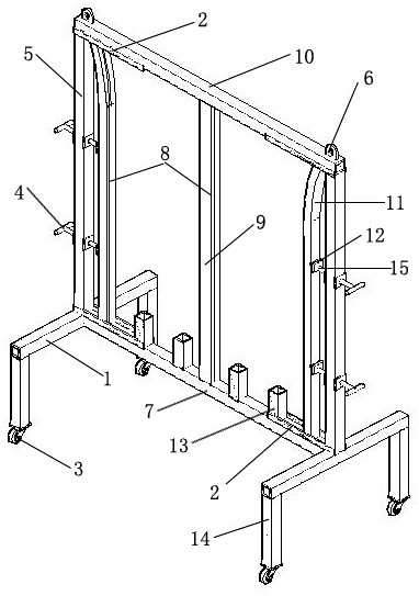
Figure 1 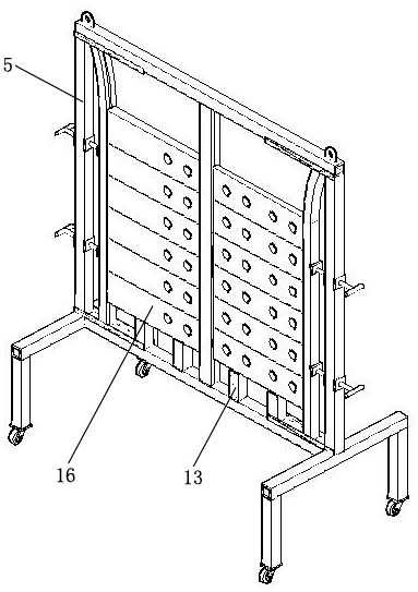
Figure 2 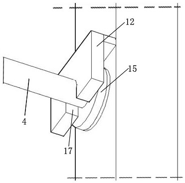
Figure 3
Abstract
Description
technical field
[0001] The present invention relates to the field of steel structure construction, in particular to a movable support for spraying and curing bolted friction test plates and a manufacturing method thereof. Background technique
[0002] The high-strength bolt friction test plate used in the process of steel structure parts processing in steel structure buildings, in many cases, the general design specification will stipulate that the surface of the test plate needs to be blast cleaned to meet the Sa2 ½ level in the GB / T 8923.1 standard. Then spray a solvent-based inorganic zinc-silicate coating with anti-slip properties on the cleaned surface. High-strength bolt friction test plate usually has a thickness of 10~30mm, a width of 90~120mm, and a length of 300~450mm. The small-sized steel plate is sprayed with paint. If it is placed horizontally on the ground or on the tire frame, it will Then the whole or part of the other side will not be able to be sprayed. Y...
Examples
Embodiment Construction
[0026] Such as figure 1 Shown is a movable bracket for spraying and curing bolted friction test plates, including a bracket 1, a support foot 14 is set at the bottom of the support 1, and a universal moving wheel 3 is set on the support foot 14; support columns are set on both sides of the support 1 5, the bracket column 5 is connected with the vertical rod 11 through the screw rod 4; the vertical vertical rod 9 is arranged in the middle of the bracket 1; The pole guide rail 2 is set, the lifting lugs 6 are arranged on both sides of the upper end surface of the upper beam 10, and the test plate spacers 13 are uniformly arranged on the lower beam 10;
[0027] A top tight iron block 12 is set on the vertical pole 11, and a rubber gasket 15 is set on the top tight iron block 12. The top of the pole 11 is curved. The pole 11 is slidably arranged in the pole guide rail 2 . The support column 5, the vertical pole 9 and the pole 11 are all square tubes.
[0028] A method for manu...