
Automatic calibration compensation method and device for Hall flow sensor
A flow sensor, automatic calibration technology, applied in test/calibration devices, measurement devices, and electromagnetic flowmeters to detect fluid flow, etc., can solve problems such as flowmeter calibration that cannot be automatically batched and liquid density is variable, and achieve good expansion. The effect of stability, simple measurement and accurate weight data
Patent Information
- Authority / Receiving Office
- CN · China
- Current Assignee / Owner
- Publication Date
- 2021-09-07
Smart Images
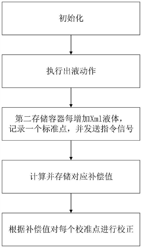
Figure 1 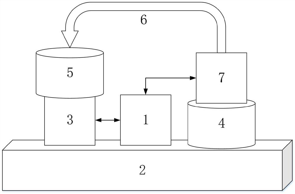
Figure 2 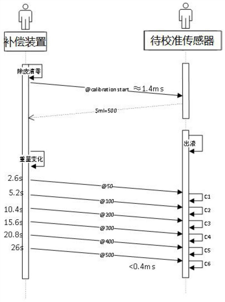
Figure 3
Abstract
Description
technical field
[0001] The invention relates to the field of flowmeter calibration, in particular to an automatic calibration and compensation method and device for a Hall flow sensor. Background technique
[0002] Hall flowmeter is a kind of Hall flowmeter based on displacement sensing. Its working principle is that the impeller rotates under the impetus of fluid, which drives the screw to rotate, so that the magnetic system moves up and down. The higher the flow rate, the larger the displacement. Then the displacement is detected by the Hall device to obtain the flow velocity and flow rate. At present, the Hall flowmeter has been widely used in public taps, milk machines, coffee machines and other terminal equipment. Its flow can be counted in real time, and various applications can be completed through supporting control algorithms. These applications generally have higher requirements on the accuracy of the flow rate. However, in practical applications, due to individua...
Examples
Embodiment 1
[0039] Such as figure 1 As shown, an automatic calibration and compensation method for a Hall flow sensor includes the following steps:
[0040] S1: Initialize the calibration device; the initialization includes performing weight calibration and tare operations. Wherein, the weight calibration step only needs to be performed before the first use, and does not need to be repeated after calibration.
[0041] S2: Execute the liquid discharge action, and transport the measurement liquid from the first storage container to the second storage container through the sensor to be calibrated; wherein, the volume of the measurement liquid=the maximum range of the sensor to be calibrated+transport loss value, the The magnitude of the transmission loss value is preset according to the type and volume of the liquid to be measured.
[0042] S3: Every time Xml of the weight of the measurement liquid increases in the second storage container, it is recorded as a calibration point, and an ins...
Embodiment 2
[0049] Such as figure 2 As shown, an automatic calibration and compensation device for a Hall flow sensor includes a control module 1 , a workbench 2 and a weighing assembly electrically connected to the control module 1 .
[0050] The weighing assembly includes a weight sensor 3 and a liquid outlet module; the liquid outlet module includes a first storage container 4, a second storage container 5, and a liquid outlet pipe 6, and the first storage container 4 passes through the waiting The calibration sensor 7 and the liquid outlet pipe 6 transfer the liquid to the second storage container 5 ; the weight sensor 3 is used to detect the weight of the second storage container 5 .
[0051] The workbench 2 is used for installing the sensor 7 to be calibrated, the control module 1 and the weighing assembly.
[0052] The control module 1 is electrically connected to the sensor 7 to be calibrated. The weight sensor 3 collects weight data through an AD sampling module. Wherein, the...
Embodiment 3
[0057] This embodiment is a specific application example of using the device described in embodiment 2 to implement the method of embodiment 1.
[0058] After actual testing, the present invention can accurately measure the number of pulse deviations of each calibration point after a full-scale discharge, and the corrected and compensated sensor to be calibrated is obtained based on this method. Then carry out quantitative liquid verification to it, the flow rate error range measured at each calibration point is less than 2ml, and the calibration point is randomly sampled, and the measured error is less than 3ml.
[0059] In addition, if image 3 As shown, according to the liquid discharge speed of the tested sensor to be calibrated, the liquid discharge time of 500ml liquid is 26 seconds, and the entire calibration process takes about 30 seconds, and does not increase with the increase of the number of calibration points.