
Rainwater pipe gallery with rainwater and sewage diversion function
A rainwater and sewage diversion, rainwater pipe technology, applied in the direction of sewage removal, sewer pipeline system, water/sewage treatment, etc., can solve the problems of difficult management, small actual income, large burial depth, etc., to achieve the effect of relieving pressure
Patent Information
- Authority / Receiving Office
- CN · China
- Current Assignee / Owner
- Publication Date
- 2021-10-22
- Estimated Expiration
- Not applicable · inactive patent
Smart Images
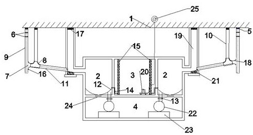
Figure 1 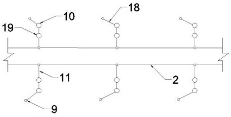
Figure 2 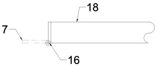
Figure 3
Abstract
Description
technical field
[0001] The invention belongs to the technical field of urban rainwater pipe gallery, in particular to a rainwater pipe gallery for diverting rain and sewage. Background technique
[0002] In recent years, there have been frequent occurrences of "waterlogging every time it rains" and "seeing the sea" in the city. The sponge city puts forward requirements for urban waterlogging prevention and rainwater resources, and hopes to use the inner space of the pipe gallery for rainwater regulation and storage, enhance the waterlogging prevention of corresponding areas and promote the comprehensive utilization of rainwater. At present, the rainwater entry corridor is mainly faced with the problems of large buried depth, large section size, difficult management, high construction cost but low actual income. At the same time, the existing pipe corridor does not divert the rainwater and sewage, which increases the pressure on the sewage treatment plant. . Contents of th...
Examples
Embodiment Construction
[0022] In order to further illustrate the present invention, the present invention will be described in detail below in conjunction with the accompanying drawings and embodiments, but they should not be construed as limiting the protection scope of the present invention. A rainwater pipe gallery for diverting rain and sewage, such as Figure 1-4 As shown, the rainwater cabin 2 is symmetrically distributed along the axis of the water storage cabin 3, the sewage cabin 4 is located below the water storage cabin 3 and the rainwater cabin 2, and the rainwater cabin 2 is connected to the road surface 1 through the rainwater cabin inspection well 19; The water pipe 14 is in communication with the storage tank 3, and the bottom plate of the rainwater tank 2 is provided with a groove 12 to avoid sediment deposition, and is connected with the sewage tank 4 through the control valve 13 and the maintenance channel 24; the sewage tank 4 is provided with a special sewage pipeline 22. The se...