
Electrical equipment single-chip microcomputer protection equipment
A technology for protecting equipment and electrical equipment, applied in the direction of electrical equipment casing/cabinet/drawer, electrical components, sealed casing, etc. The effect of fixing instability and increasing the fixing ability
Patent Information
- Authority / Receiving Office
- CN · China
- Patent Type
- Applications(China)
- Current Assignee / Owner
- Publication Date
- 2021-11-26
- Estimated Expiration
- Not applicable · inactive patent
Smart Images
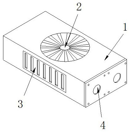
Figure 1 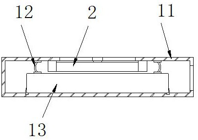
Figure 2 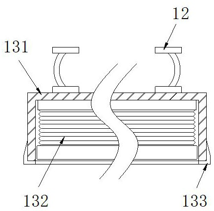
Figure 3
Abstract
Description
technical field
[0001] The invention belongs to the technical field of electrical equipment, and more specifically relates to a single-chip microcomputer protection equipment for electrical equipment. Background technique
[0002] The single-chip microcomputer protection device is used to protect the single-chip microcomputer. The protection equipment is composed of a protective shell and a storage compartment. The single-chip microcomputer is wrapped by the protective shell to prevent the single-chip microcomputer from being affected by the outside world. However, in winter, the single-chip microcomputer will generate heat when it is working. When the device stops working The temperature of the single-chip microcomputer drops, thermal expansion and contraction lead to a gap between the outer casing of the protection device and the storage compartment, and the water vapor in the air easily enters the inside of the cooling protection device through the gap, and the water vapor...
Examples
Embodiment 1
[0028] as attached figure 1 To attach Figure 6 Shown:
[0029] The invention provides a single-chip microcomputer protection device for electrical equipment, the structure of which includes a protective cover 1, a fan 2, an air inlet 3, and a connection port 4. The front of the protective cover 1 is embedded and connected, and the outer side of the wiring port 4 is embedded and connected with the right side of the protective cover 1. The protective cover 1 includes a casing 11, a pressure plate 12, and a storage compartment 13. The middle part of the upper end of the casing 11 is connected to the outer side of the fan 2. Embedded connection, the pressure plate 12 is embedded and connected between the inner side of the upper end of the housing 11 and the upper side of the placement bin 13 , and the lower side of the placement bin 13 is glued to the inner side of the lower end of the outer shell 11 .
[0030] Wherein, the storage bin 13 includes a bin wall 131, an expander 13...
Embodiment 2
[0037] as attached Figure 7 to attach Figure 9 Shown:
[0038] Wherein, the fixed foot 133 includes a rotating shaft 33a, a stabilizer 33b, and a fixed plate 33c, the outer side of the rotating shaft 33a is axially connected with the middle part of the lower end of the warehouse wall 131, and the left side of the stabilizer 33b is axially connected with the outer side of the fixed plate 33c. The upper end of the fixing plate 33c is connected with the outer shaft of the rotating shaft 33a, and the number of the stabilizers 33b is two, and they are installed symmetrically on the left and right sides of the warehouse wall 131, so that the stabilizers 33b can fix both sides of the bottom of the warehouse wall 131, improving the The fixing capacity of the warehouse wall 131.
[0039] Wherein, the stabilizer 33b includes a movable plate b1, a limit bin b2, a movable plate b3, and a sleeve b4, the left side of the movable plate b1 is bonded to the right side of the limit bin b2, ...