
Non-woven fabric slitting equipment
A technology of non-woven fabrics and equipment, applied in the field of non-woven fabric cutting equipment, can solve the problems of reducing the service life of the equipment, increasing the occurrence of accidents, and low degree of automation, so as to reduce the length error, increase the friction force, and improve the automation. degree of effect
Patent Information
- Authority / Receiving Office
- CN · China
- Patent Type
- Applications(China)
- Current Assignee / Owner
- Publication Date
- 2022-02-01
- Estimated Expiration
- Not applicable · inactive patent
Smart Images
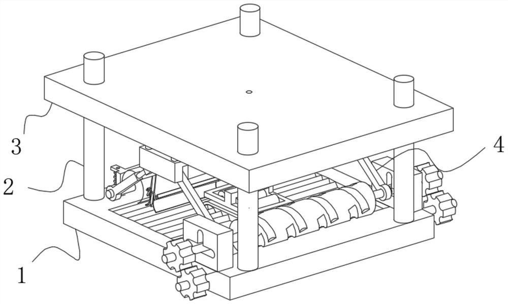
Figure 1 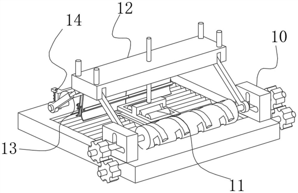
Figure 2 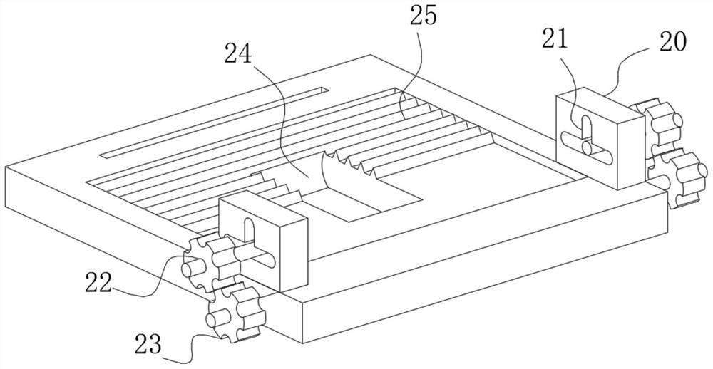
Figure 3
Abstract
Description
technical field
[0001] The invention belongs to the field of non-woven fabric cutting, in particular to non-woven fabric cutting equipment. Background technique
[0002] Non-woven fabrics, also known as non-woven fabrics, needle-punched cotton, needle-punched non-woven fabrics, etc., are made of polyester fiber and polyester fiber (PET for short) and are made by acupuncture. It has the characteristics of moisture-proof, breathable, flexible, light weight, flame retardant, non-toxic and tasteless, low price, and recyclable. It can be used in different industries, such as sound insulation, heat insulation, electric heaters, masks, clothing, medical, filling materials, etc.
[0003] Due to the low degree of automation in the production and cutting of traditional non-woven fabrics, most of the operations need to be completed manually, which makes the produced non-woven fabrics prone to wrinkles, resulting in large length errors, and because the cutter is exposed, During manual...
Examples
Embodiment Construction
[0023] use Figure 1-Figure 7 A non-woven fabric slitting device according to an embodiment of the present invention is described as follows.
[0024] Such as Figure 1-Figure 7 As shown, a kind of non-woven fabric cutting equipment of the present invention comprises a bottom plate 1;: the upper surface of the bottom plate 1 is fixedly connected with a guide rod 2, and the outer surface of the top end of the guide rod 2 is slidably connected with a top plate 3, and the bottom of the top plate 3 is arranged Cutting mechanism 4 is arranged, and cutting mechanism 4 is positioned at the top of bottom plate 1, and cutting mechanism 4 comprises material receiving mechanism 10, and the left side of material receiving mechanism 10 is provided with feeding mechanism 11, and the top of feeding mechanism 11 is provided with tiling mechanism 12, tiling A cutter 13 is movably connected to the bottom left of the mechanism 12, and a movable plate 14 is arranged on the left side of the cutte...