
A Crack Detection Device for Double-layer Supported Bridges
A detection device and bridge technology, which is applied to measurement devices, material inspection products, measuring instrument components, etc., can solve the problems of personal safety threats, time-consuming and labor-intensive, and inconvenient use of detection personnel. The effect of improving safety
Patent Information
- Authority / Receiving Office
- CN · China
- Patent Type
- Patents(China)
- Current Assignee / Owner
- Publication Date
- 2022-04-12
Smart Images
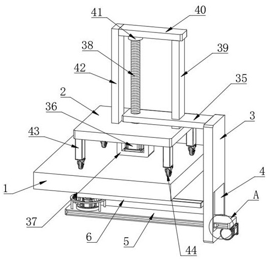
Figure 1 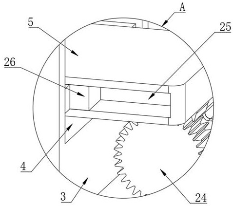
Figure 2 
Figure 3
Abstract
Description
technical field
[0001] The invention belongs to the technical field of bridge detection, in particular to a crack detection device for double-layer supported bridges. Background technique
[0002] Cracks on the surface of concrete bridges are mutations in the process of internal damage accumulation, and they are a concentrated expression of the dangerous degree of internal damage. Therefore, their information content is very large, and they are of key significance for predicting and harbingering bridge dangers. Therefore, it is necessary to analyze the cracks of bridges Detection, nip in the bud.
[0003] In the prior art, the detection of cracks is mainly carried out by hand-held detectors, which is time-consuming and laborious. When detecting cracks on the bottom of the bridge, personnel need to go under the bridge, posing a threat to the personal safety of the detection personnel, and the efficiency is low, which is not convenient for practical use. Contents of the inve...
Examples
Embodiment 1
[0035] Embodiment one, by Figure 1 to Figure 10 Given, the present invention comprises bridge body 1 and moving seat 2, and moving seat 2 is positioned at the top of bridge body 1, and one side of moving seat 2 is provided with lifting seat 3, and one side of lifting seat 3 is provided with rectangular hole 4, and lifting seat One side of 3 is provided with a movable plate 5, which runs through the rectangular hole 4, and the movable plate 5 and the lifting seat 3 are connected by moving out the movable mechanism. Connected by detecting the lifting mechanism;
[0036]The multi-directional detection assembly includes a rotating plate 6 arranged above the movable plate 5, the movable plate 5 and the rotating plate 6 are connected by a first drive motor 7, and the top of the rotating plate 6 is provided with a first chute 8, and inside the first chute 8 A first slider 9 is provided, a crack detector body 10 is provided on the top of the first slider 9, and a first threaded colu...
Embodiment 2
[0037] Embodiment two, on the basis of embodiment one, by Figure 4 , Figure 5 , Figure 7 , Figure 8 with Figure 9 Given, the top of the movable plate 5 is fixedly connected with a fixed ring 19, the top of the fixed ring 19 is provided with an annular groove 20, the annular groove 20 is provided with a rotating ring 21, and the top of the rotating ring 21 passes through the bottom of the rotating plate 6 The two second fixed columns 22 are connected, the cross section of the rotating ring 21 and the annular groove 20 are T-shaped structures, the first gear 16 and the gear ring 17 are meshed, the first bevel gear 13 and the second bevel gear 14 The rotating support unit includes a support plate 30 arranged below the fixed shaft 15, the support plate 30 and the fixed shaft 15 are connected by a second bearing 31, and the bottoms of the support plate 30 and the rotating plate 6 are connected by two first connecting frames 32 , and the first connecting frame 32 is an L-sh...
Embodiment 3
[0039] Embodiment three, on the basis of embodiment one, by figure 2 , image 3 , Image 6 with Figure 10 Given, moving out the movable mechanism includes a toothed plate 23 arranged at the bottom of the movable plate 5, the toothed plate 23 is fixedly connected with the movable plate 5, one side of the lifting seat 3 is provided with a second gear 24, and both sides of the movable plate 5 are provided with The second chute 25, the inner walls on both sides of the rectangular hole 4 are fixedly connected with the first connecting plate 27, one side of the first connecting plate 27 is fixedly connected with the second slider 26, and one side of the lifting seat 3 is fixedly connected with the second A mounting seat 29, the first mounting seat 29 and the second gear 24 are connected by the second drive motor 28, the second slide block 26 is located in the second chute 25, the second gear 24 is located at the bottom of the tooth plate 23, and the second The gear 24 is meshed...