
Vacuum casting furnace main shaft lifting rod protection device
A technology of protection device and lifting rod, applied in the direction of casting mold, casting mold composition, casting equipment, etc., can solve the problem of shortening the service life of the spindle, and achieve the effect of reducing the number of maintenance and cost, improving the applicability and improving the use efficiency.
Patent Information
- Authority / Receiving Office
- CN · China
- Patent Type
- Applications(China)
- Current Assignee / Owner
- Publication Date
- 2022-03-22
Smart Images
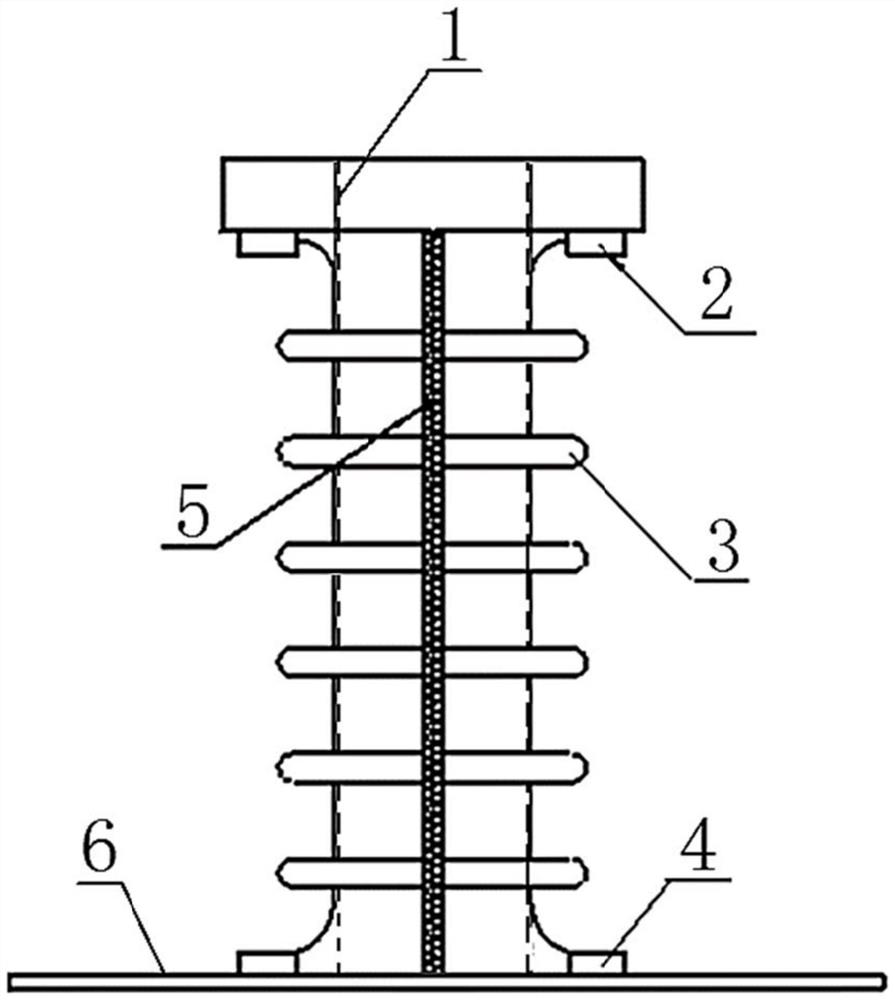
Figure 1
Abstract
Description
technical field
[0001] The invention relates to the field of investment casting precision casting vacuum melting furnaces, and relates to aviation and aerospace engines, in particular to a protection device for a main shaft lifting rod of a vacuum melting casting furnace, which is used to protect the safety and reliability of the core part of the main shaft system. Background technique
[0002] Some investment precision castings require vacuum in the environment during pouring, so they need to be poured in vacuum casting equipment. The main content of the vacuum pouring process is to pour the liquid whose melting temperature reaches the required temperature into the mold shell that reaches the specified temperature in the equipment with a vacuum degree that meets the requirements.
[0003] During the pouring process, the form shell is raised to the pouring chamber through the main shaft lifting rod. If the pouring operation is improper, the high-temperature liquid above the ...
Examples
Embodiment 1
[0052] ALD three-chamber vacuum furnace
[0053] 1) Make a protective cover 2 matching the main shaft of the ALD furnace, and arrange an elastic refractory plastic material along the axial direction of the main shaft.
[0054] 2) Make the first fixing part 2 and the second fixing part 4 in the present invention, so that the top end of the protective cover 2 can be tightly connected with the bottom surface of the lifting rod table through the first fixing part 2, and the bottom end can pass through the second fixing part for one week. Part 4 is seamlessly connected with pit 6.
[0055] 3) Make the zipper 5 of the present invention, zip it from top to bottom along the axial direction of the protective cover 2, connect the protective cover 2 for one week, and keep the gap between the main shaft elevating rod 1 and the protective cover 2 at 12mm.
[0056] 4) Install the manufactured lifting rod corrugated protective cover on the outside of the main shaft lifting rod 1, fasten the...
Embodiment 2
[0060] 1) Make a supporting protective cover 2 for a large-scale 100kg vacuum furnace, and arrange an elastic refractory plastic material along the axial direction of the main shaft.
[0061] 2) Make the first fixing part 2 and the second fixing part 4 in the present invention, so that the top end of the protective cover 2 can be tightly connected with the bottom surface of the lifting rod table through the first fixing part 2, and the bottom end can pass through the second fixing part for one week. Part 4 is seamlessly connected with pit 6.
[0062] 3) Make the zipper 5 of the present invention, zip from top to bottom along the axial direction of the protective cover 2, connect the protective cover 2 for one week, and keep the gap between the main shaft elevating rod 1 and the protective cover 2 at 15 mm.
[0063] 4) Install the manufactured lifting rod corrugated protective cover on the outside of the main shaft lifting rod 1, fasten the upper and lower ends with four bolts ...