
Engine valve driving device
A technology of engine valves and driving devices, which is applied in the direction of engine components, combustion engines, machines/engines, etc., can solve the problems of engine height increase, etc., and achieve the effects of reducing clearance, shortening reaction time, and reducing costs
Patent Information
- Authority / Receiving Office
- CN · China
- Current Assignee / Owner
- Publication Date
- 2022-07-08
Smart Images
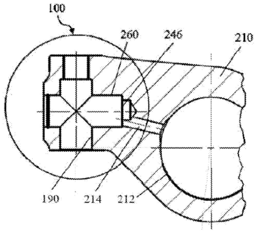
Figure 1 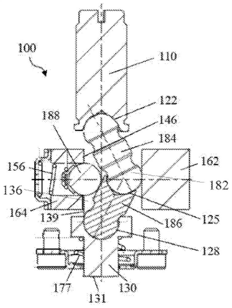
Figure 2 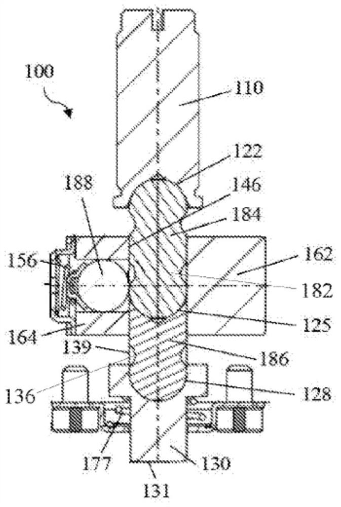
Figure 3
Abstract
Description
technical field
[0001] The present invention relates to an engine valve drive device. Background technique
[0002] Conventional methods for actuating valves of vehicle engines are well known in the art and have been used for over a hundred years. However, due to the additional demands on engine emission control and engine braking, more and more engines require additional valve movements to be added to conventional valve movements, such as those for exhaust gas recirculation and those for engine braking. valve movement.
[0003] A conventional engine brake is a box-type hydraulic drive mechanism placed on top of the engine. To accommodate this type of engine brake, a gasket was added between the cylinder head and the engine cover to create extra space. This adds height, weight and cost to the engine. These problems are caused by viewing the engine braking system as an additional accessory to the engine rather than an integral part of the engine.
[0004] Another disadva...
Examples
Embodiment Construction
[0116] According to an embodiment of the present invention, as figure 1 , 2 As shown in FIG. and 3 , the engine valve drive 100 may include a housing 210 , a start piston 162 , a drive piston 130 , a linkage mechanism 182 , and one or more of a guide mechanism 137 , an anti-rotation mechanism 138 , and a positioning mechanism 150 .
[0117] The case 210 may be the rocker arm or valve bridge of the engine. In this embodiment, the box body 210 is a rocker arm, which can be similar to the rocker arm (210b) of EP2384396. like figure 1 As shown, the rocker arm is mounted on a rocker arm shaft (not shown) through hole 212 .
[0118] like figure 1 As shown, the housing 210 includes an actuation piston bore 260 and a drive piston bore 190 . Preferably, the actuation piston bore 260 and the drive piston bore 190 intersect each other perpendicularly. The activation piston 162 is slidably disposed in the activation piston bore 260 . The drive piston 130 is disposed in the drive pi...