
Refrigeration cycle apparatus
A technology of circulation device and refrigerant, which is applied in gas cycle refrigerators, irreversible cycle compressors, refrigerators, etc., can solve problems such as pressure rise and reliability decline of refrigeration cycle devices.
Patent Information
- Authority / Receiving Office
- CN · China
- Patent Type
- Patents(China)
- Current Assignee / Owner
- Publication Date
- 2007-02-14
- Estimated Expiration
- Not applicable · inactive patent
Smart Images
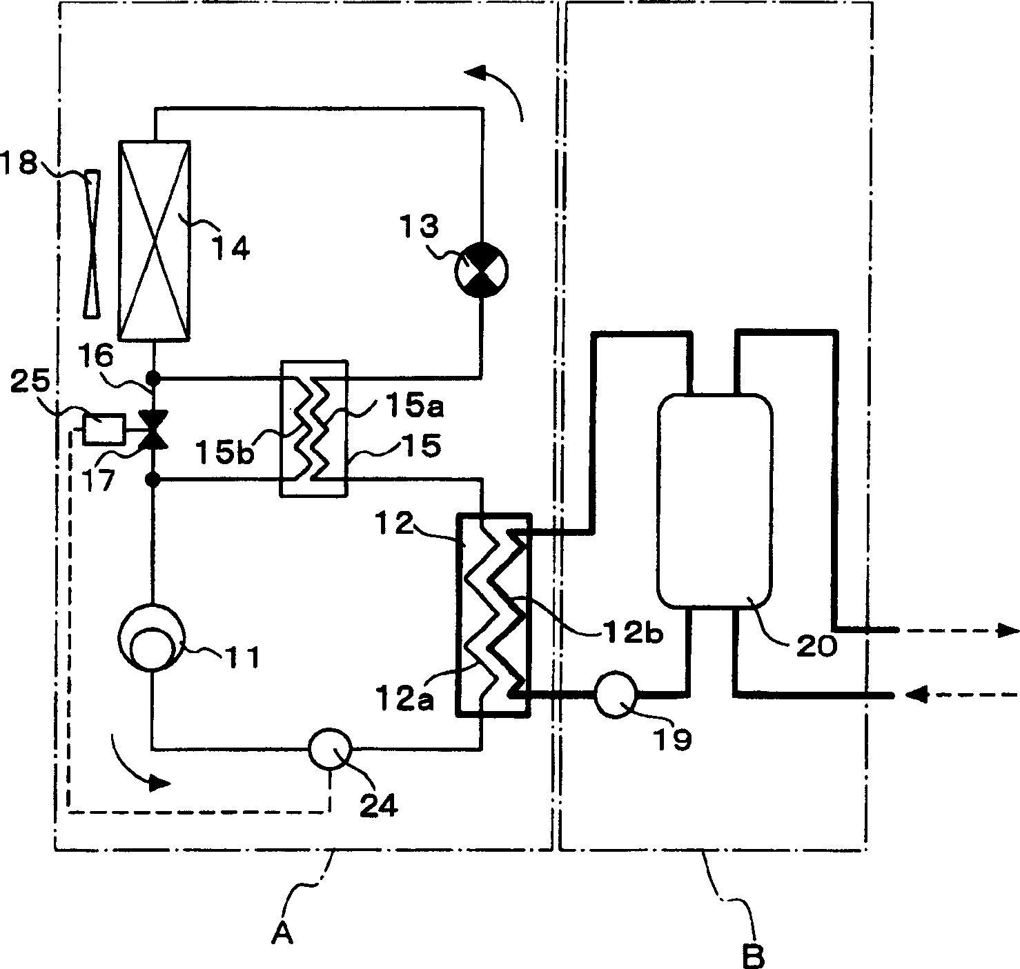
Figure 1 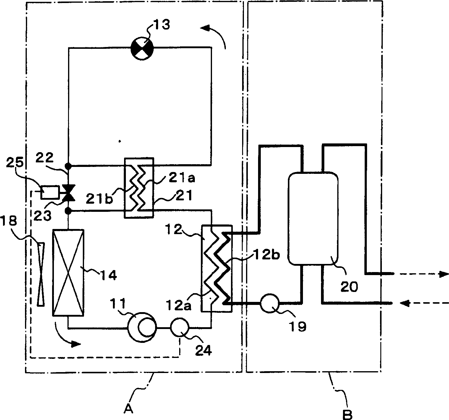
Figure 2 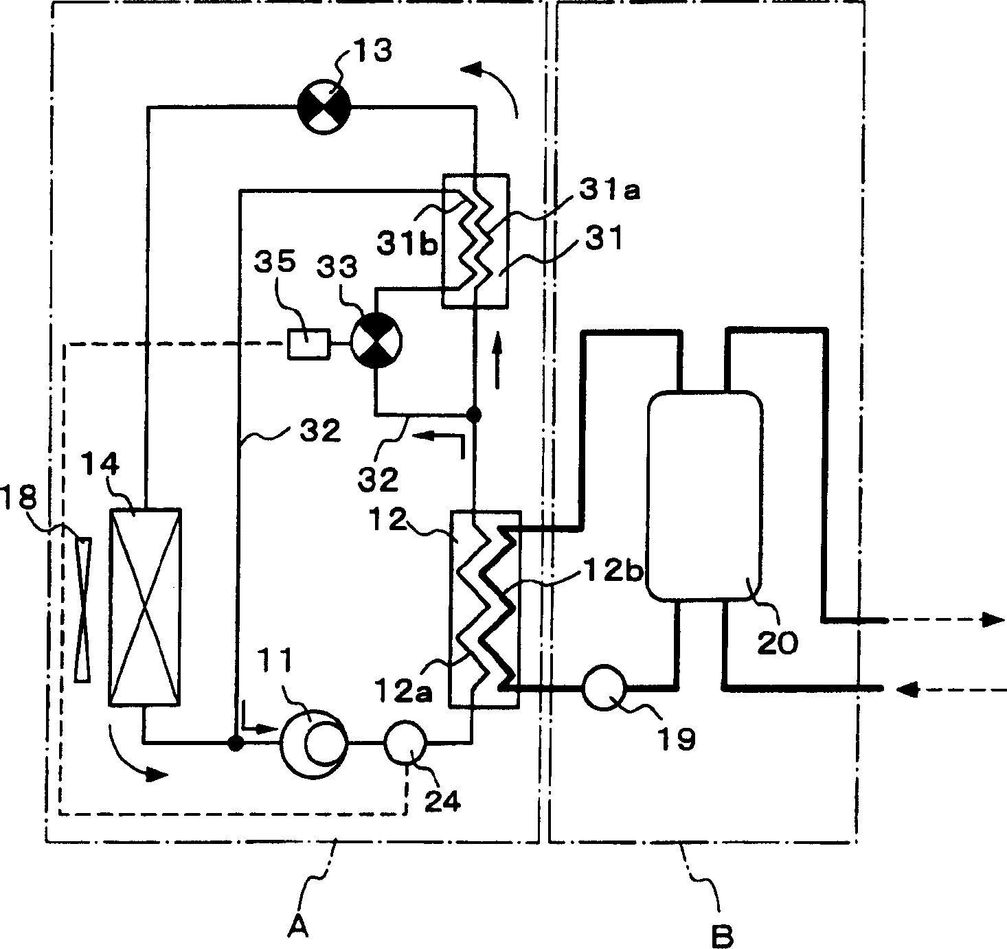
Figure 3
Abstract
Description
technical field
[0001] The present invention relates to an apparatus as a refrigerant refrigerating cycle using a refrigerant capable of being in a supercritical state on a high-pressure side. Background technique
[0002] Conventionally, hydrocarbons containing fluorine atoms (Freons) have been used as refrigerants to be enclosed in refrigeration cycle apparatuses. However, Freon has the property of depleting the ozone layer and has a long lifetime in the atmosphere, so that it has a large greenhouse effect, and therefore affects global warming, so it cannot be said to be a satisfactory refrigerant. Therefore, it has been proposed to use carbon dioxide, ethane, etc. as refrigerants instead of Freon-based refrigeration cycle devices (for example, refer to Patent Document 1). The ozone destruction coefficient of carbon dioxide, ethane, etc. is zero, and the global warming coefficient is comparable to that of Freon. is also very small.
[0003] Refrigerants such as carbon di...
Examples
Embodiment 1
[0024] Hereinafter, a refrigeration cycle apparatus according to an embodiment of the present invention will be described by taking a hot water supplier as an example with reference to the drawings. The present invention is not limited by this embodiment. figure 1 It is a configuration diagram showing the refrigeration cycle apparatus according to the first embodiment of the present invention.
[0025] The refrigeration cycle apparatus of the first embodiment includes a refrigerant circuit A and a fluid circuit B; the refrigerant circuit A includes a compressor 11, a refrigerant flow path 12a of a radiator 12 as a heat exchanger for hot water supply, and an internal heat exchange circuit. The high-pressure side refrigerant flow path 15a of the unit 15, the pressure reducer 13, the evaporator 14, the low-pressure side refrigerant flow path 15b of the internal heat exchange unit 15, etc.; Road 12b, hot water supply tank 20, etc.
[0026] In the above-mentioned refrigerant cir...
Embodiment 2
[0036] figure 2 It is a configuration diagram showing a refrigeration cycle apparatus according to a second embodiment of the present invention. In this embodiment, the same constituent elements as in the first embodiment are adopted and figure 1 The same symbols are used and their descriptions are omitted, and the configuration and operation different from those of the first embodiment of this embodiment will be described below.
[0037] In the refrigeration cycle apparatus of the second embodiment, the high-pressure side refrigerant flow path 21a of the internal heat exchange unit 21 is provided between the radiator 12 (refrigerant flow path 12a) outlet and the pressure reducer 13 inlet, and the low-pressure side refrigerant The flow path 21b is provided between the outlet of the decompressor 13 and the inlet of the evaporator 14, and is cooled in the radiator 12 by the low-pressure side refrigerant flowing in the low-pressure side refrigerant flow path 21b between the out...
Embodiment 3
[0044] image 3 It is a configuration diagram showing a refrigeration cycle apparatus according to a third embodiment of the present invention. In this embodiment, the same constituent elements as in the first embodiment are adopted and figure 1 The same symbols are used and their descriptions are omitted, and the configuration and operation different from those of the first embodiment of this embodiment will be described below.
[0045] In the refrigeration cycle apparatus of the third embodiment, the high-pressure side refrigerant flow path 31a of the internal heat exchange unit 31 is provided between the outlet of the radiator 12 (refrigerant flow path 12a) and the inlet of the pressure reducer 13, and the low-pressure side refrigerant flow path The flow path 31b is provided in a bypass circuit 32 that branches between the radiator 12 (refrigerant flow path 12a) and the high-pressure side refrigerant flow path 31a of the internal heat exchange unit 31, and passes through ...