
Digital precision phase-shift method and phase shifter
A phase-shifting and precise technology, applied in the field of phase shifters, can solve problems such as difficult discrete circuit implementation, fluctuation of phase-shifting phase value, poor modification flexibility, etc., and achieve the effect of stable phase shift, stable phase and low cost
Patent Information
- Authority / Receiving Office
- CN · China
- Patent Type
- Applications(China)
- Current Assignee / Owner
- Publication Date
- 2007-02-14
Smart Images
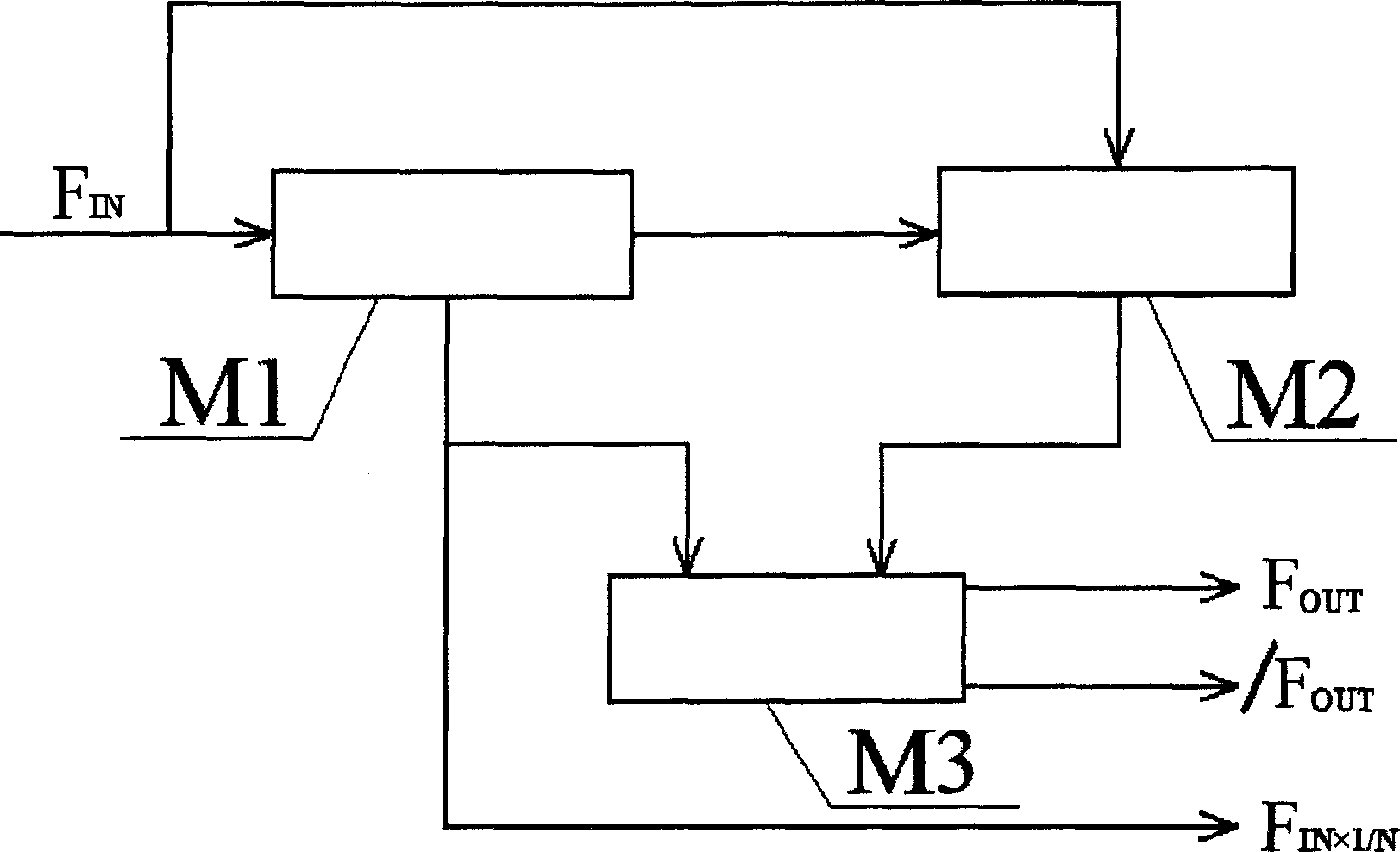
Figure 1 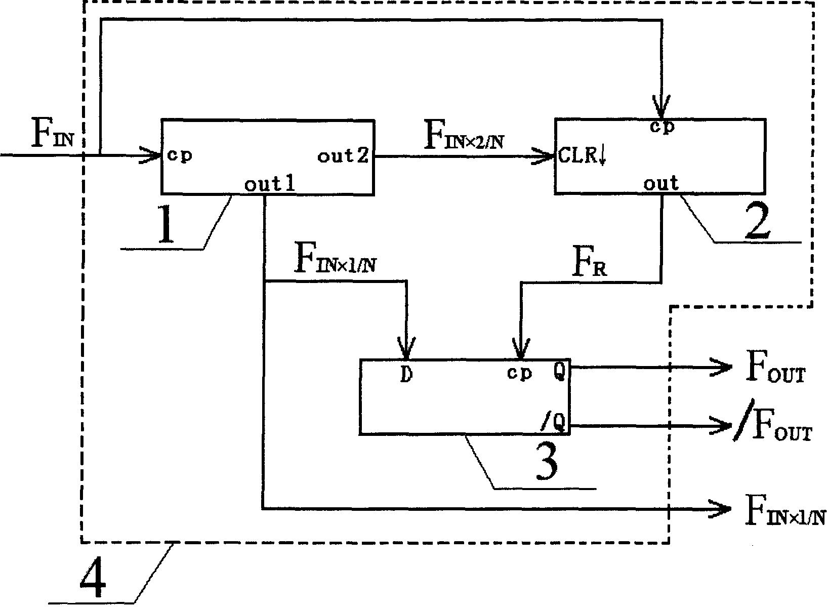
Figure 2 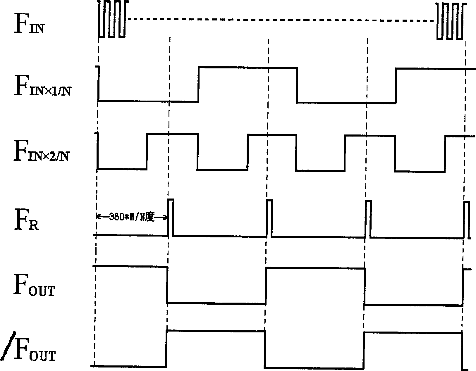
Figure 3
Abstract
Description
technical field
[0001] The invention relates to a digital precision phase shifting method for an atomic clock, and also relates to a phase shifter, which can be widely used in various atomic clocks and precision time equipment. Background technique
[0002] In atomic clocks and precision time equipment circuits, there are various methods to achieve phase shifting, but they can be roughly divided into three categories. One is analog phase shifting, which uses amplifiers plus RC phase shifting networks or shift filters. The mechanism is to use the phase-frequency characteristics of the filter network to achieve the purpose of phase shifting, but due to the discrete linear components (such as capacitors, resistors, etc.) It is directly related to power supply fluctuations, so the phase shifting phase value has large fluctuations and it is difficult to make the phase shifting accuracy high; the other is to use the transmission delay time (propagation delay) of the digital gate c...
Examples
Embodiment Construction
[0029] 1. Part selection
[0030] A. CPLD4 uses EPM1270T144C5 from ALTERA company;
[0031] B, 24-bit counter module 1 is implemented in Verilog HDL language inside CPLD4;
[0032] C. The 23-bit preset counter module 2 is implemented in Verilog HDL language inside CPLD4;
[0033] D, D flip-flop module 3 is realized with Verilog HDL language inside CPLD4.
[0034] 2. Specific implementation methods
[0035] Depend on figure 1 As shown, the implementation steps of a phase shifting method are as follows:
[0036] ①Input signal F IN Connect to the clock input terminal of the n-bit counter M1, and the counter M1 outputs two synchronous square wave signals, one of which is F IN×1 / N , the other signal is F IN×2 / N , F IN×1 / N The frequency is F IN one-nth of N, and F IN×2 / N The frequency is F IN×1 / N Twice of , where N≤2 n And the value of N is determined by the control parameters of the counter M1, F IN×1 / N That is, the square wave signal to be phase-shifted;
[0037] ②In...