
Magnetic sensor
a technology of magnetic sensor and output signal, applied in the field of magnetic sensor, can solve the problems of preventing the variation in the above-mentioned conversion efficiency, large variation in efficiency, and large variation in output signal, so as to reduce or eliminate the variation in output signal
Patent Information
- Authority / Receiving Office
- US · United States
- Patent Type
- Patents(United States)
- Current Assignee / Owner
- Publication Date
- 2019-09-03
Smart Images
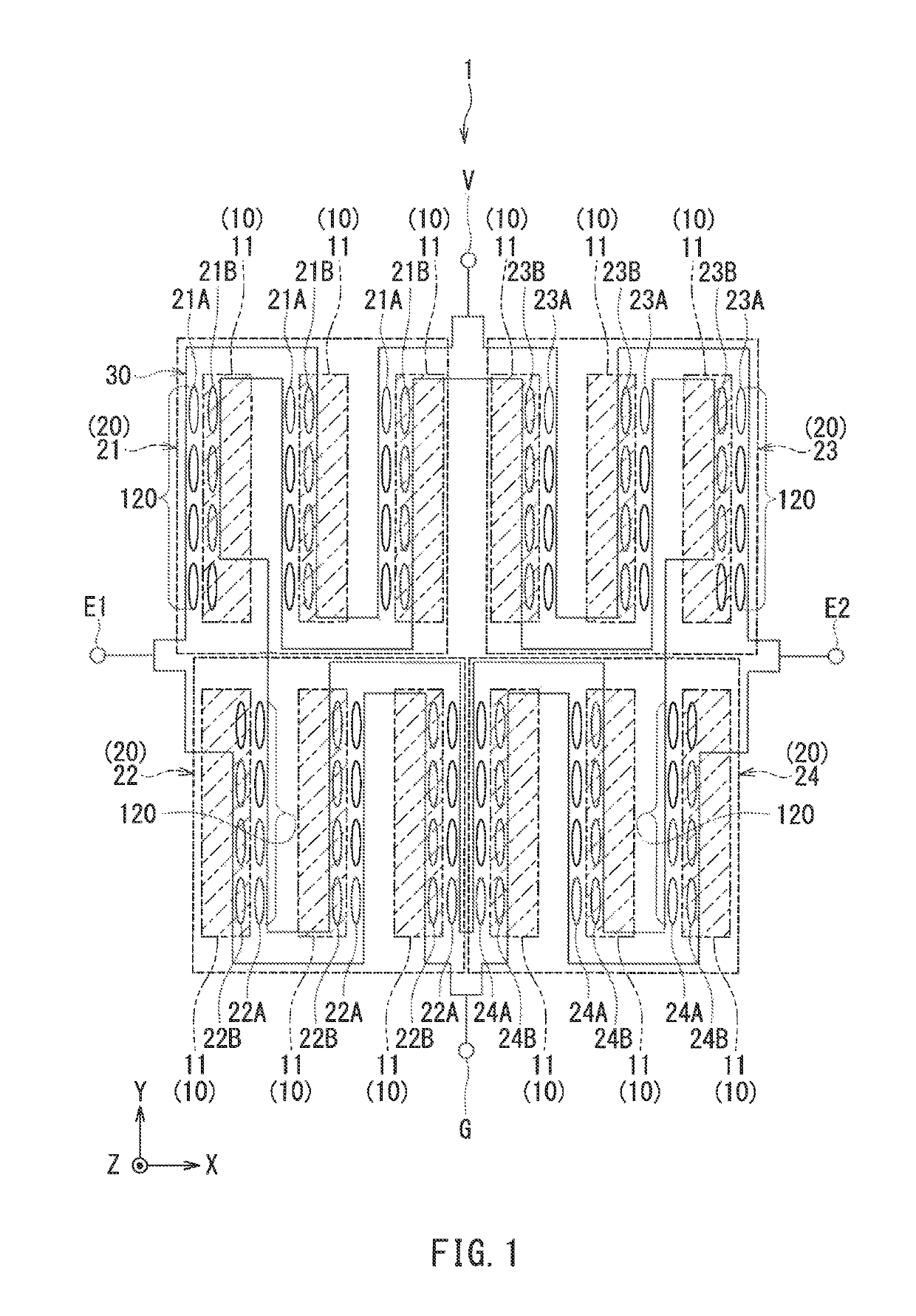
Figure 1 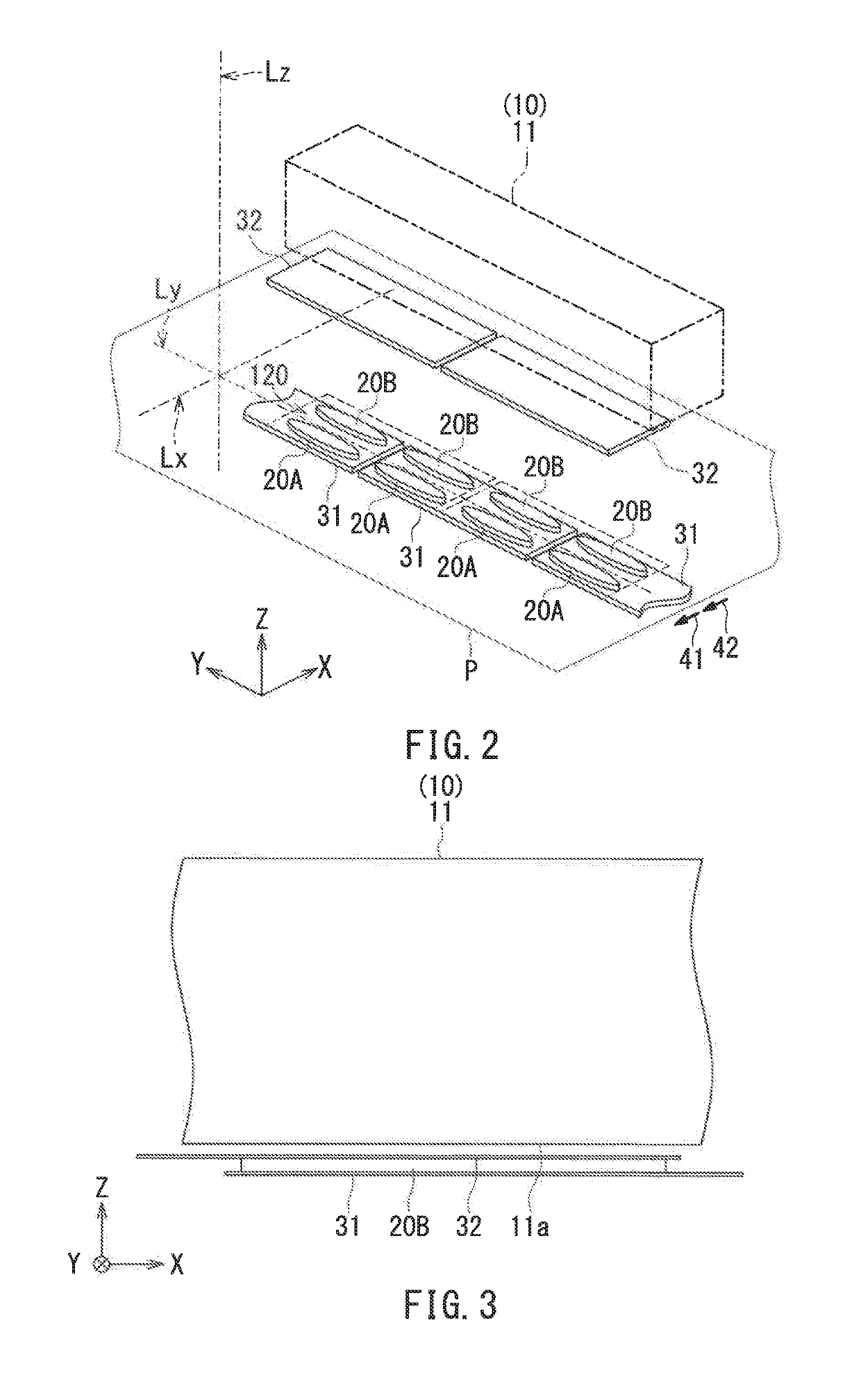
Figure 2 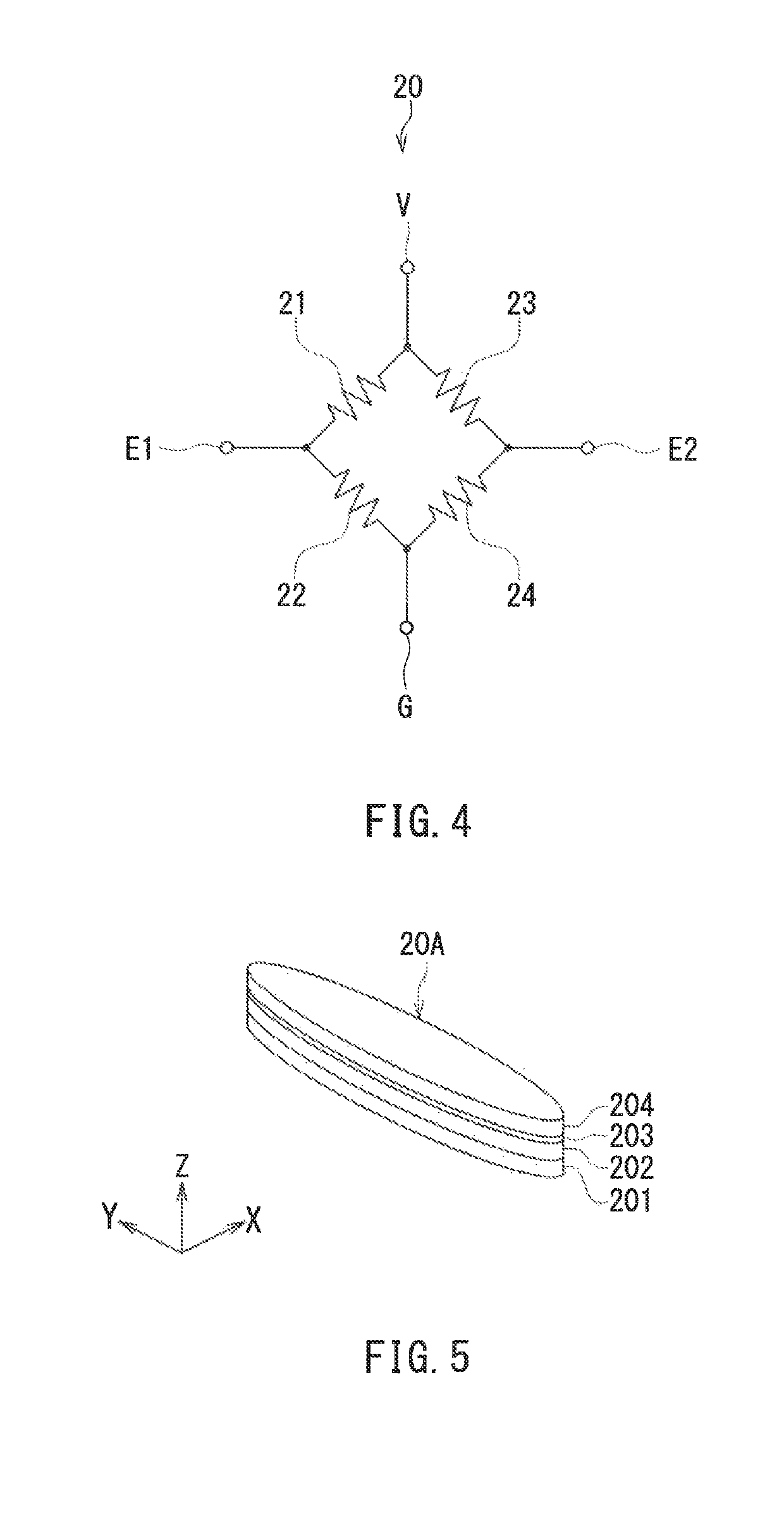
Figure 3
Abstract
Description
BACKGROUND OF THE INVENTION1. Field of the Invention
[0001] The present invention relates to a magnetic sensor capable of detecting, through the use of a magnetic detection element, a magnetic field in a direction other than the direction to which the magnetic detection element has sensitivity.2. Description of the Related Art
[0002] Nowadays, some mobile telecommunication devices such as mobile phones may be configured with geomagnetic sensors. It is required of the geomagnetic sensors intended for such use to be small in size and capable of detecting three-dimensional directions of an external magnetic field. Such geomagnetic sensors are implemented using magnetic sensors. Magnetic sensors provided with a plurality of magnetic detection elements on a substrate are known. The magnetic detection elements may be magnetoresistive elements, for example.
[0003] In many cases, the magnetic detection elements provided on a substrate are configured to detect a magnetic field in a direction paral...
Examples
first embodiment
[0055]Preferred embodiments of the present invention will now be described in detail with reference to the drawings. First, reference is made to FIG. 6 to describe the configuration of a magnetic sensor unit including a magnetic sensor according to a first embodiment of the invention. FIG. 6 is a perspective view of the magnetic sensor unit 100. The magnetic sensor unit 100 includes: a substrate 101 having a top surface 101a; a magnetic sensor 1 according to the first embodiment; and two magnetic sensors 2 and 3 other than the magnetic sensor 1. The magnetic sensors 1 to 3 are aligned on the top surface 101a of the substrate 101.
[0056]Now, we define X, Y and Z directions as shown in FIG. 6. The X, Y and Z directions are orthogonal to one another. In the present embodiment, the X direction is from the magnetic sensor 3 to the magnetic sensor 1, and the Z direction is a direction perpendicular to the top surface 101a of the substrate 101. Further, −X, −Y, and −Z directions refer to di...
second embodiment
[0120]A second embodiment of the present invention will now be described. First, reference is made to FIG. 9 and FIG. 10 to describe the configuration of the magnetic sensor according to the second embodiment. FIG. 9 is an explanatory diagram schematically illustrating the configuration of the magnetic sensor according to the second embodiment. FIG. 10 is a partial, exploded perspective view of the magnetic sensor according to the second embodiment. The magnetic sensor 1 according to the second embodiment differs from the first embodiment in the following ways. The magnetic sensor 1 according to the second embodiment includes a wiring layer 130 in place of the wiring layer 30 of the first embodiment. The wiring layer 130 establishes electrical connection between the first and second magnetic detection elements 20A and 20B. The general shape of the wiring layer 130 is meandering when viewed in the Z direction. The wiring layer 130 includes a plurality of lower electrodes 131 and a pl...
third embodiment
[0130]A third embodiment of the present invention will now be described. First, reference is made to FIG. 11 and FIG. 12 to describe the configuration of the magnetic sensor according to the third embodiment. FIG. 11 is an explanatory diagram schematically illustrating the configuration of the magnetic sensor according to the third embodiment. FIG. 12 is a partial, exploded perspective view of the magnetic sensor according to the third embodiment. The magnetic sensor 1 according to the third embodiment differs from the first embodiment in the following ways. In the third embodiment, each of the first to fourth resistor sections 21 to 24 of the magnetic field detection unit 20 includes a single magnetic detection element train 220 in place of the plurality of magnetic detection element trains 120 of the first embodiment.
[0131]The magnetic detection element train 220 includes a first portion in which a plurality of first magnetic detection elements 20A are aligned in the Y direction, ...