
Three-dimensional printing apparatus
Patent Information
- Authority / Receiving Office
- US · United States
- Current Assignee / Owner
- Publication Date
- 2016-12-22
- Estimated Expiration
- Not applicable · inactive patent
Smart Images
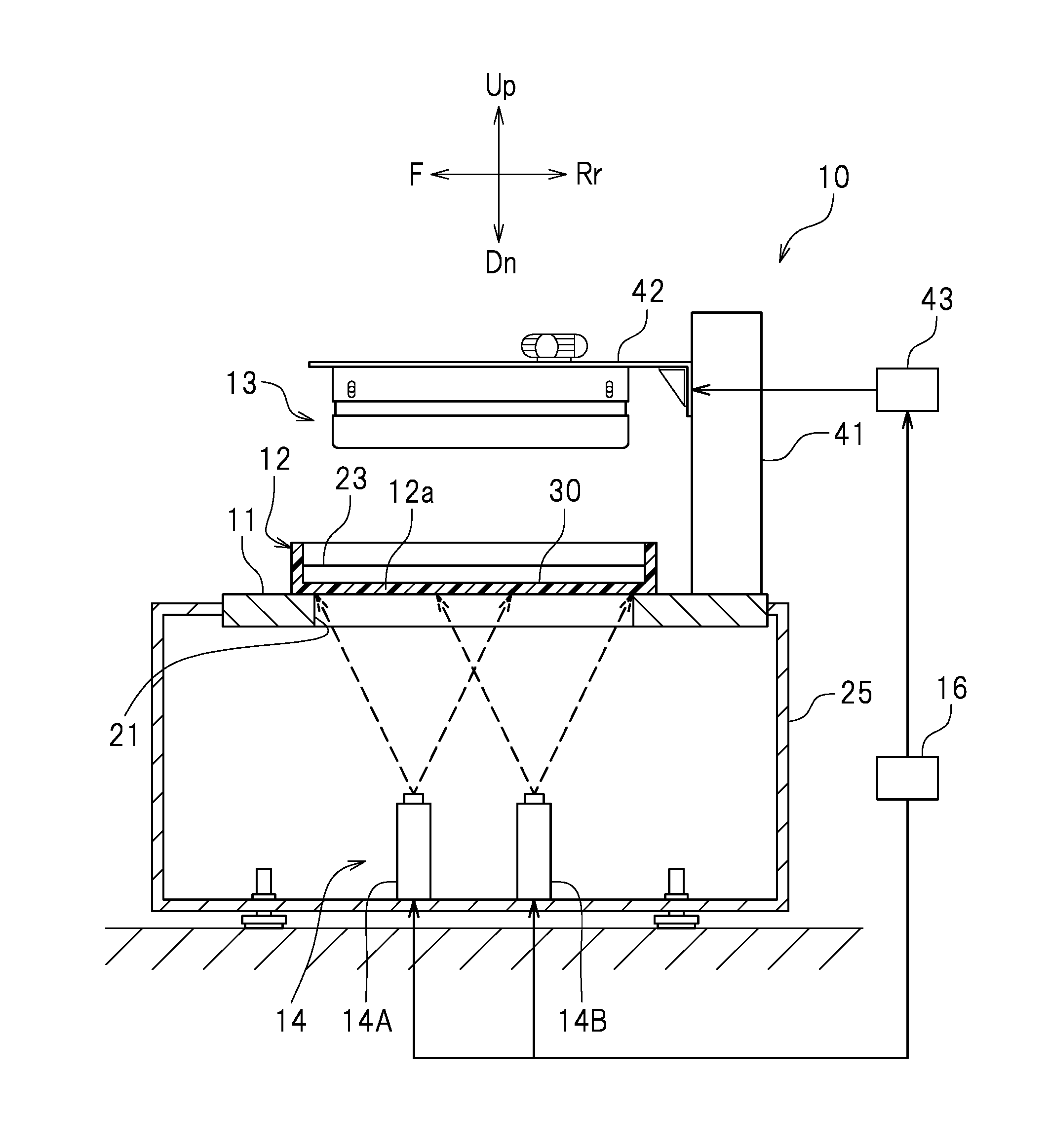
Figure 1 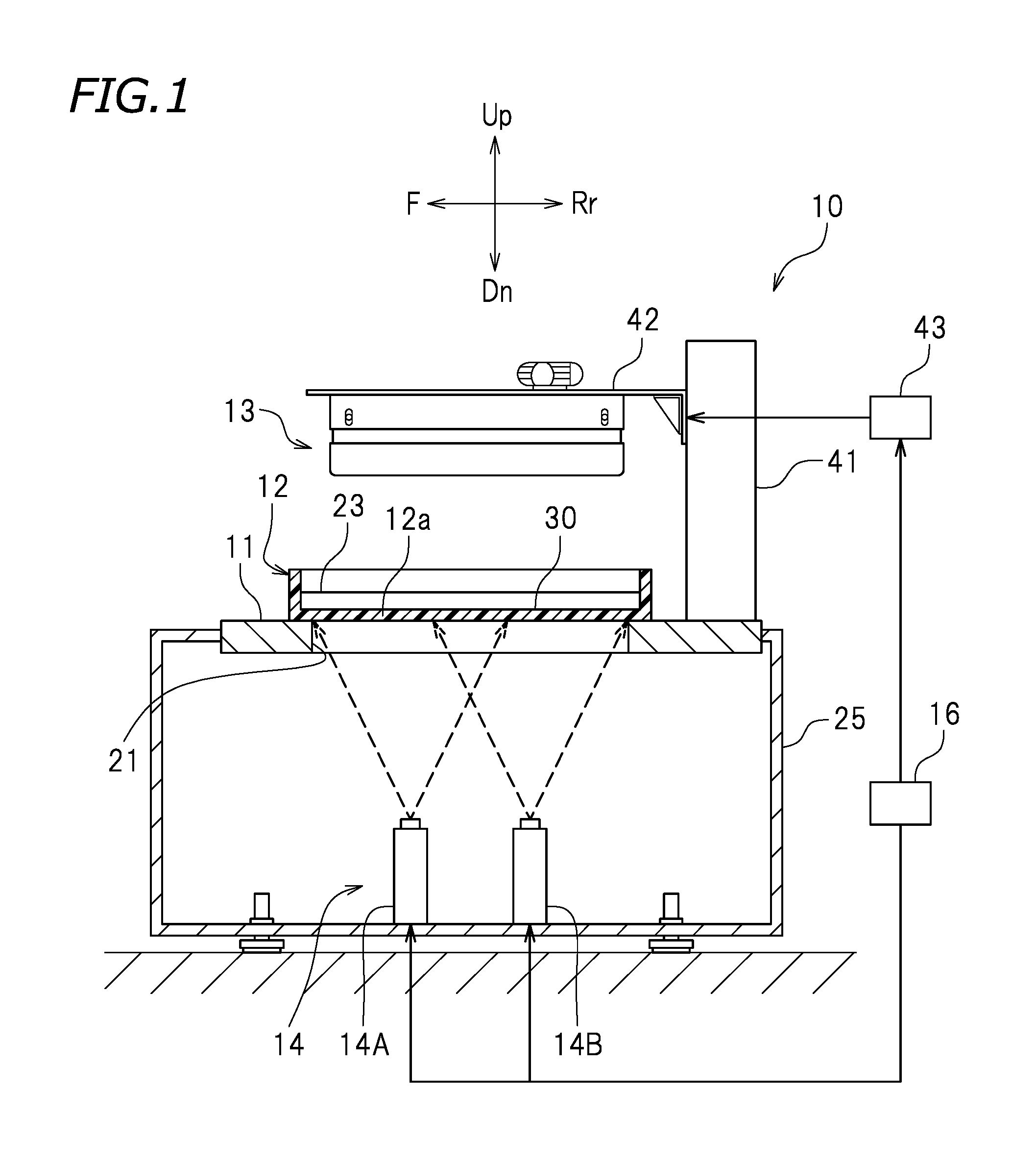
Figure 2 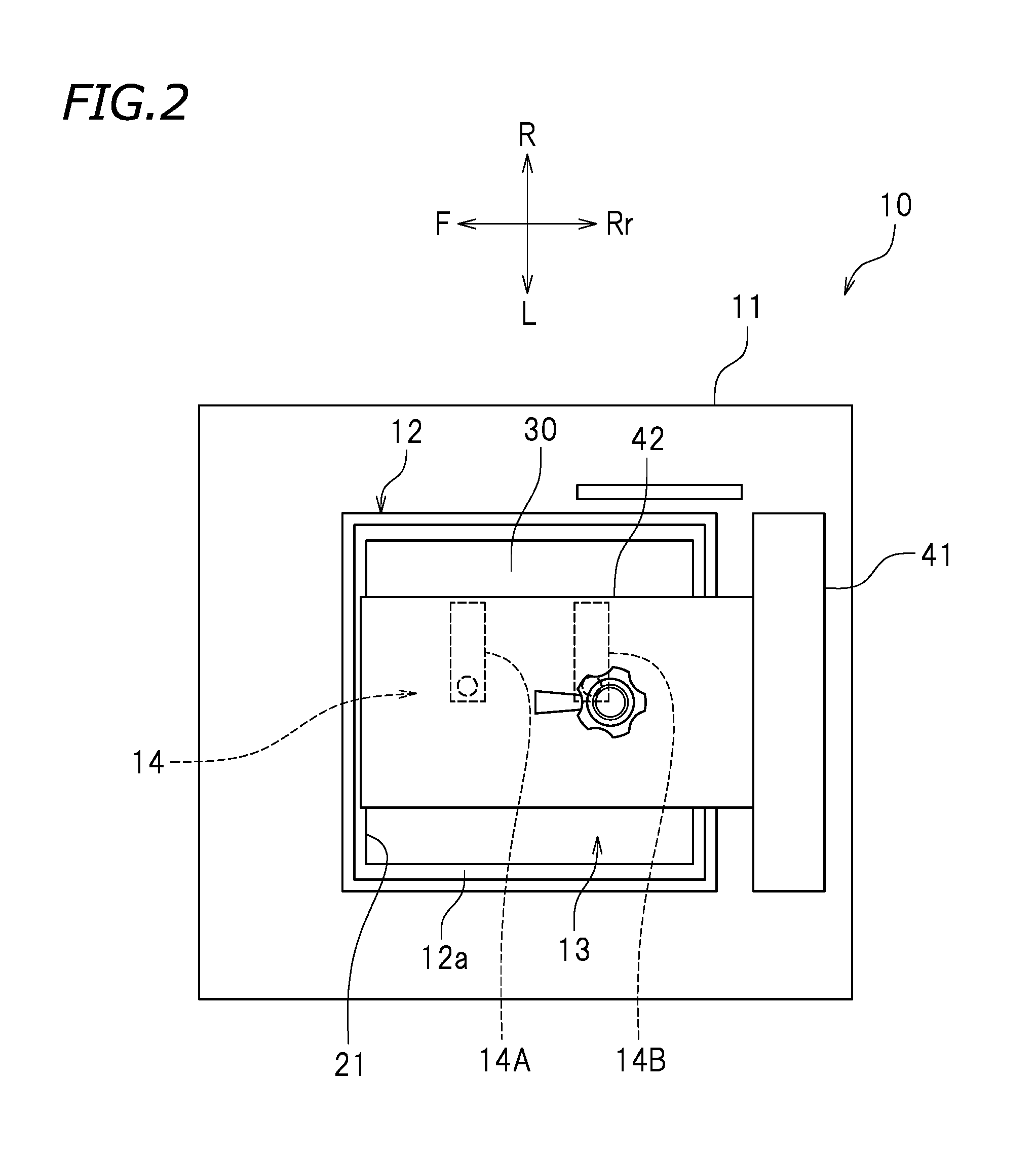
Figure 3
Abstract
Description
[0001] This application claims priority to Patent Application No. 2015-122787 filed in Japan on Jun. 18, 2015, the entire contents of which are hereby incorporated by reference.BACKGROUND OF THE INVENTION
[0002] 1. Field of the Invention
[0003] The present invention relates to three-dimensional printing apparatuses.
[0004] 2. Description of the Related Art
[0005] A known three-dimensional printing apparatus applies light to liquid photo-curable resin stored in a tank so as to cure the photo-curable resin, thus printing a three-dimensional object.
[0006] For example, JP 2003-39564 A discloses a three-dimensional printing apparatus including a table provided with an opening; a tank that is placed on the table and stores photo-curable resin; a raisable and lowerable holder disposed above the tank; and a projecting device disposed below the table. The projecting device projects a cross-sectional image representing a cross-sectional shape of a three-dimensional object to be printed. The cross-secti...
Examples
first preferred embodiment
[0032]FIG. 1 is a cross-sectional view of a three-dimensional printing apparatus 10 according to a first preferred embodiment of the present invention. FIG. 2 is a plan view of the three-dimensional printing apparatus 10. The reference signs F, Rr, R, L, Up, and Dn in the drawings respectively represent front, rear, right, left, up, and down. The reference sign X in the drawings represents an X axis extending in the front-rear direction. The reference sign Y in the drawings represents a Y axis extending in the right-left direction. These directions are, however, defined merely for the sake of convenience and thus do not limit in any way how the three-dimensional printing apparatus 10 may be installed.
[0033]The three-dimensional printing apparatus 10 is configured to print a three-dimensional object. In accordance with cross-sectional images representing cross-sectional shapes of a three-dimensional object to be printed, the three-dimensional printing apparatus 10 cures liquid photo-...
second preferred embodiment
[0050]As illustrated in FIG. 6, the projector 14 preferably includes a third projector 14C in addition to the first projector 14A and the second projector 14B. The controller 16 is connected to the third projector 14C as well as to the first projector 14A and the second projector 14B. Similarly to the first projector 14A and the second projector 14B, the third projector 14C receives a cross-sectional image signal from the controller 16.
[0051]As illustrated in FIG. 7, the image projecting surface 30 preferably includes the first area 30A, the second area 30B adjacent to the first area 30A, the third area 30C adjacent to the second area 30B, a fourth area 30D adjacent to the first area 30A, a fifth area 30E adjacent to the second area 30B and the fourth area 30D, a sixth area 30F adjacent to the third area 30C and the fifth area 30E, and a seventh area 30G adjacent to the fourth area 30D, the fifth area 30E, and the sixth area 30F. The fourth to sixth areas 30D to 30F are located left...
third preferred embodiment
[0068]As illustrated in FIG. 11, the projector 14 preferably includes a fourth projector 14D and a fifth projector 14E in addition to the first projector 14A and the second projector 14B. The controller 16 is connected to the fourth projector 14D and the fifth projector 14E as well as to the first projector 14A and the second projector 14B. Similarly to the first projector 14A and the second projector 14B, the fourth projector 14D and the fifth projector 14E each receive a cross-sectional image signal from the controller 16. Component or elements similar to those in the second preferred embodiment will be omitted as unnecessary.
[0069]As illustrated in FIG. 12, the image projecting surface 30 preferably includes the first area 30A, the second area 30B adjacent to the first area 30A, the third area 30C adjacent to the second area 30B, the fourth area 30D adjacent to the first area 30A, the fifth area 30E adjacent to the second area 30B and the fourth area 30D, the sixth area 30F adjac...