
Scroll type fluid machine
a fluid machine and scrolling technology, applied in the direction of machines/engines, liquid fuel engines, rotary piston liquid engines, etc., can solve the problems of reducing the efficiency affecting the reliability of the fluid machine, and the difficulty of providing highly accurate machined sliding surfaces to the wrap tip and the flat plate portion, so as to improve the reliability of the scrolling fluid machine, increase the frictional resistance, and reduce the effect of deformation
Patent Information
- Authority / Receiving Office
- US · United States
- Patent Type
- Applications(United States)
- Current Assignee / Owner
- Publication Date
- 2004-05-27
- Estimated Expiration
- Not applicable · inactive patent
Smart Images
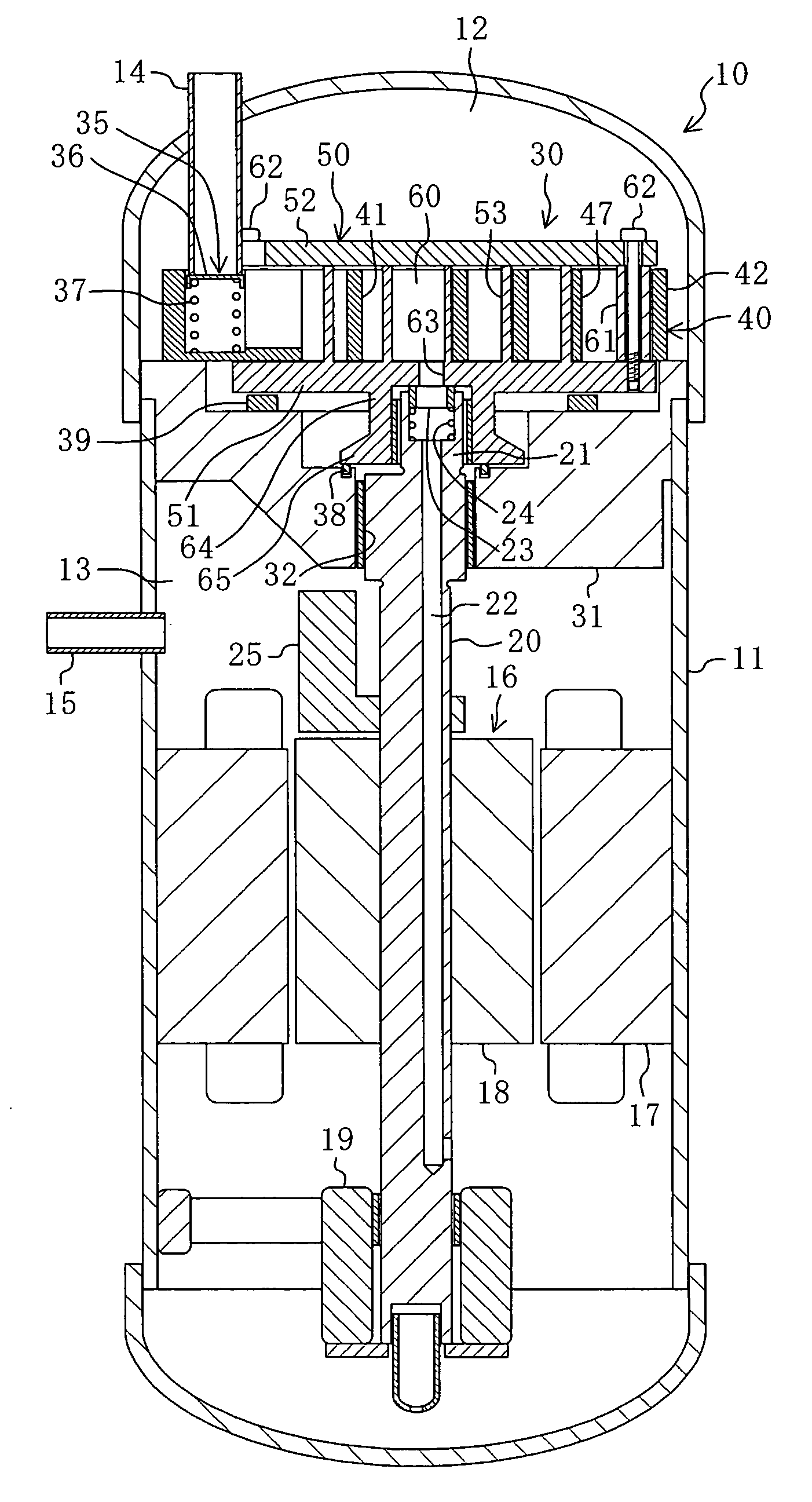
Figure 1 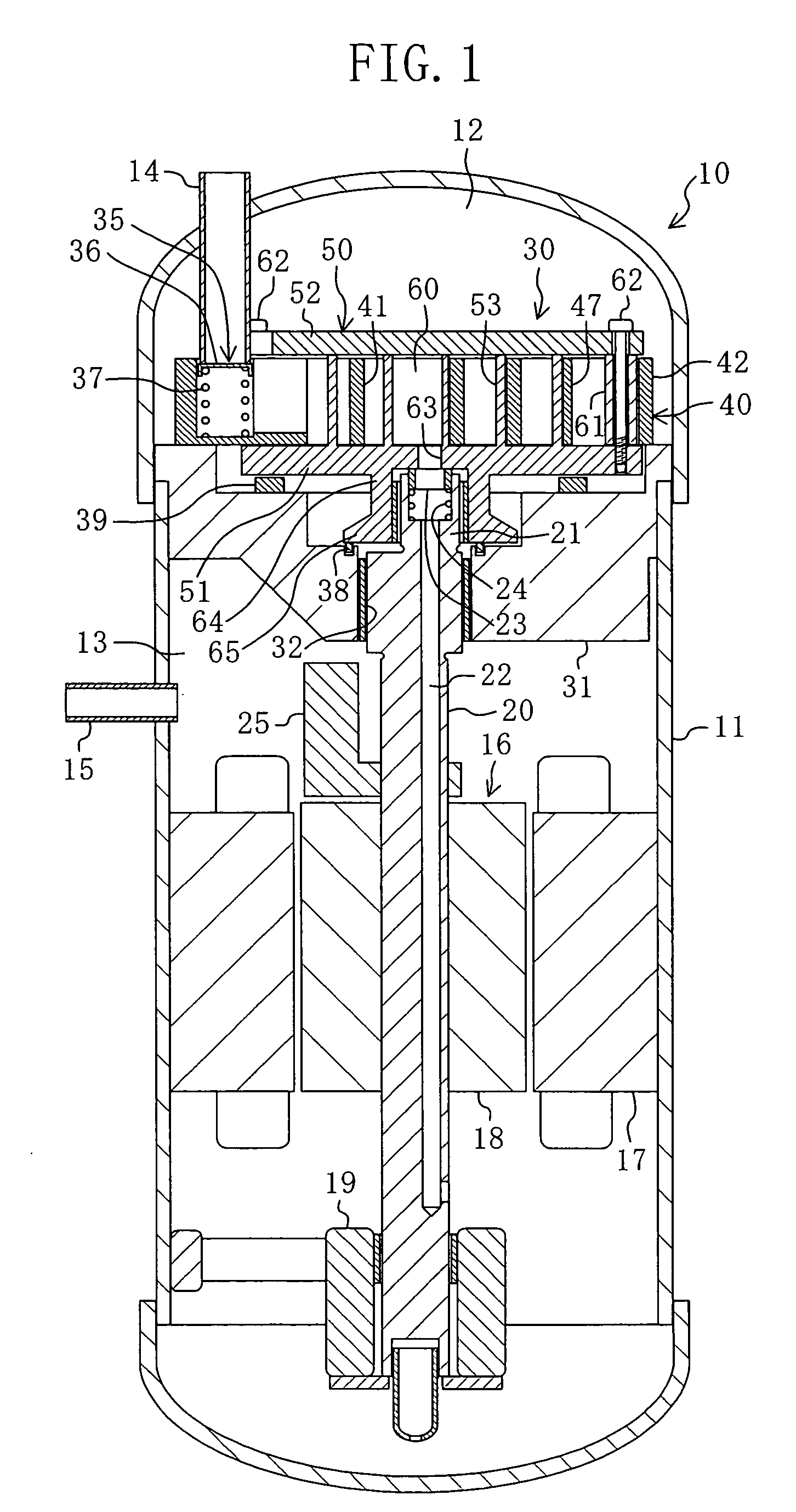
Figure 2 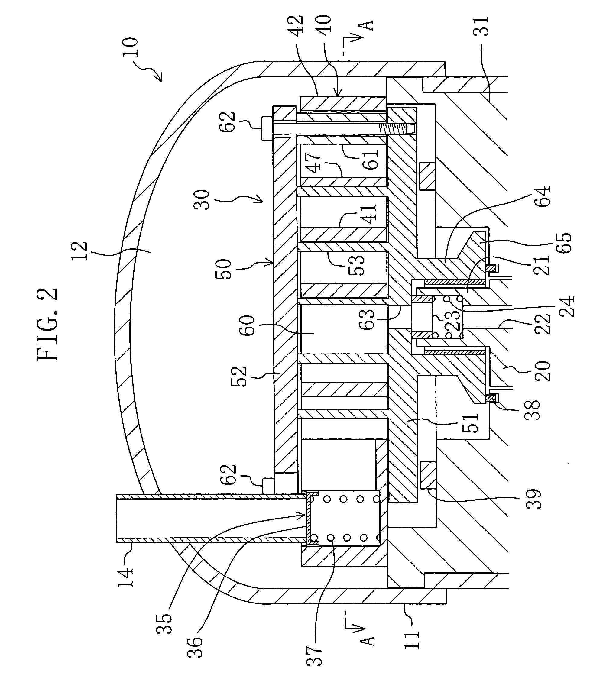
Figure 3
Abstract
Description
[0001] The present invention relates to fluid machines of the scroll type.
[0002] Scroll type fluid machines have been well known in the prior art. For example, Japanese Patent Kokai number (1994)330864 discloses a compressor composed of a scroll type fluid machine.
[0003] An arrangement of a typical scroll type fluid machine will be described below. This type of fluid machine includes a stationary scroll and a movable scroll. The stationary and movable scrolls include respective tabular flat plate portions and spiral wraps. In both the scrolls, the wraps are vertically arranged on front surface sides of the flat plate portions. Additionally, in both the scrolls the wraps are formed integrally with the flat plate portions, respectively. The stationary and movable scrolls are disposed in such an orientation that they face each other, and their respective wraps are matingly engaged with each other. The wraps, which are being engaged with each other, are sandwiched between the flat plate...
Examples
embodiment 1 of invention
[0149] A first embodiment of the present invention is a scroll compressor (10) composed of a scroll type fluid machine according to the present invention. This scroll compressor (10) is provided in a refrigerant circuit of a refrigerating apparatus.
[0150] As shown in FIG. 1, the scroll compressor (10) has a so-called hermetically sealed construction. This scroll type compressor has a casing (11) which is shaped like a longitudinal, cylindrical, hermetically sealed container. A compression mechanism (30), an electric motor (16), and a lower bearing (19) are disposed in that order (from top down) in the inside of the casing (11). Additionally, a vertically-extending driving shaft (20) serving as a rotary shaft is disposed in the inside of the casing (11).
[0151] The interior of the casing (11) is divided vertically by a housing (31) of the compression mechanism (30). In the inside of the casing (11), a space above the housing (31) becomes a low pressure chamber (12) and a space below t...
fourth modification example
[0234] Fourth Modification Example of First Embodiment
[0235] In the scroll compressor (10) of the foregoing embodiment, in the stationary scroll (40) the height of the outer peripheral portion (42) is equal to that of the stationary side wrap (41). However, instead of employing such an arrangement the following arrangement may be used.
[0236] In other words, the height of the outer peripheral portion (42) may be made somewhat greater than the height of the stationary side wrap (41) (see FIG. 14). In the present modification example, the second flat plate (52) comes into sliding contact with the upper surface of the outer peripheral portion (42) even when the movable scroll (50) is positioned at the downmost position, thereby ensuring that a clearance is always secured between the upper tip of the stationary side wrap (41) and the second flat plate (52).
[0237] Consequently, the tip of the stationary side wrap (41) is prevented from suffering damage from forceful frictional contact wit...
fifth modification example
[0240] Fifth Modification Example of First Embodiment
[0241] In the scroll compressor (10) of the foregoing embodiment, the height of the stationary side wrap (41) is constant in the stationary scroll (40). However, instead of such an arrangement the following arrangement may be employed.
[0242] To sum up, as shown in FIG. 15, the height of the stationary side wrap (41) may become gradually smaller toward the center side from the outer peripheral side of the stationary side wrap (41). In the present modification example, the upper tip surface of the stationary side wrap (41) is an inclined plane inclining downwardly toward the center side from the outer peripheral side of the stationary side wrap (41). On the other hand, the lower tip surface of the stationary side wrap (41) is an inclined plane inclining upwardly toward the center side from the outer peripheral side of the stationary side wrap (41). In addition, it may be arranged such that only the upper tip surface is inclined and ...