
Versatile attenuator
a reverse attenuator and oscillator technology, applied in the direction of code conversion, automatic control, instruments, etc., can solve the problems of inability to achieve the dynamic range of the receiver above 60 db, the effect of enhancing the effective dynamic range of the accompanying circuit and facilitating the reverse attenuation
Patent Information
- Authority / Receiving Office
- US · United States
- Patent Type
- Applications(United States)
- Current Assignee / Owner
- Publication Date
- 2006-02-02
- Estimated Expiration
- Not applicable · inactive patent
Smart Images
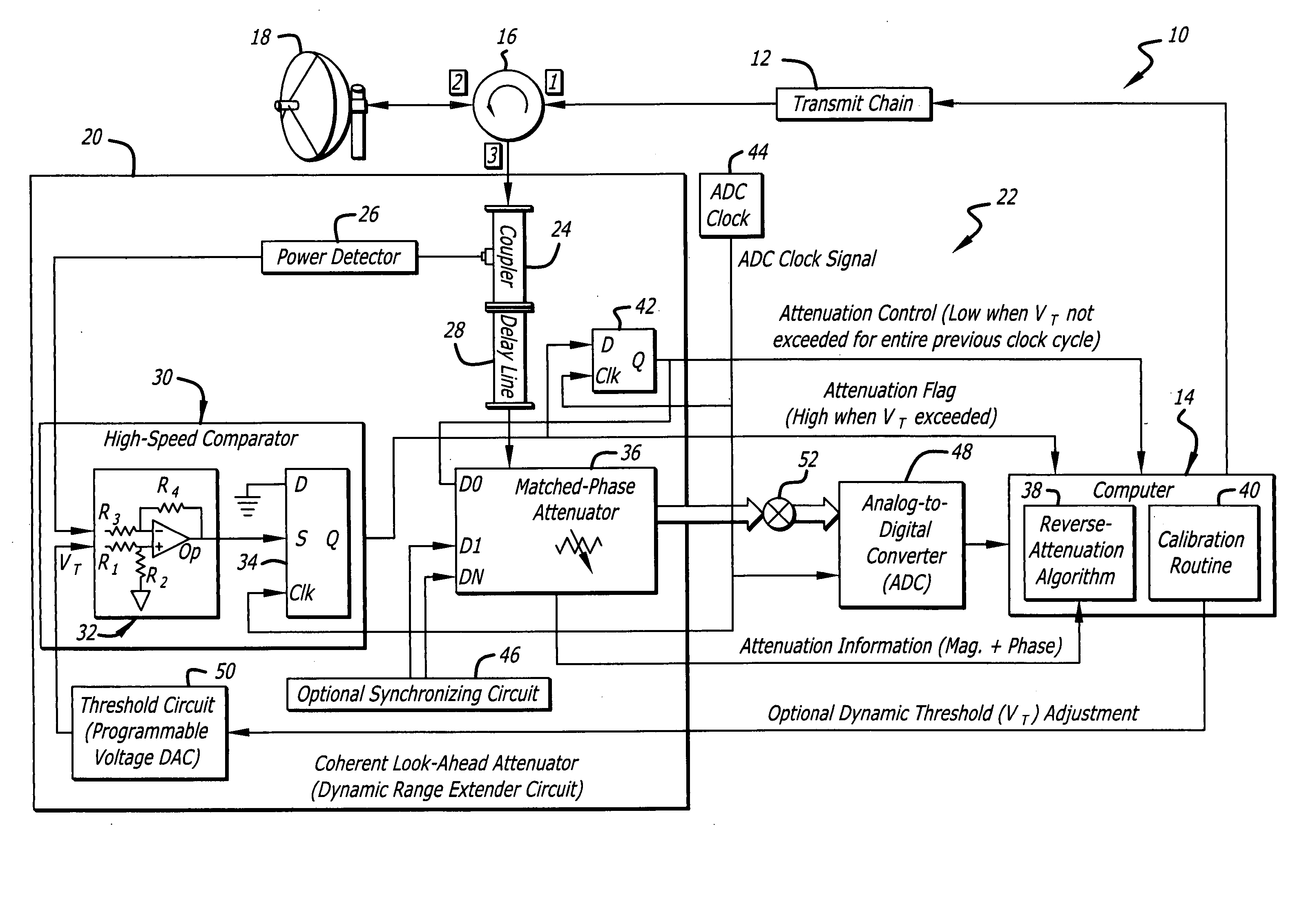
Figure 1 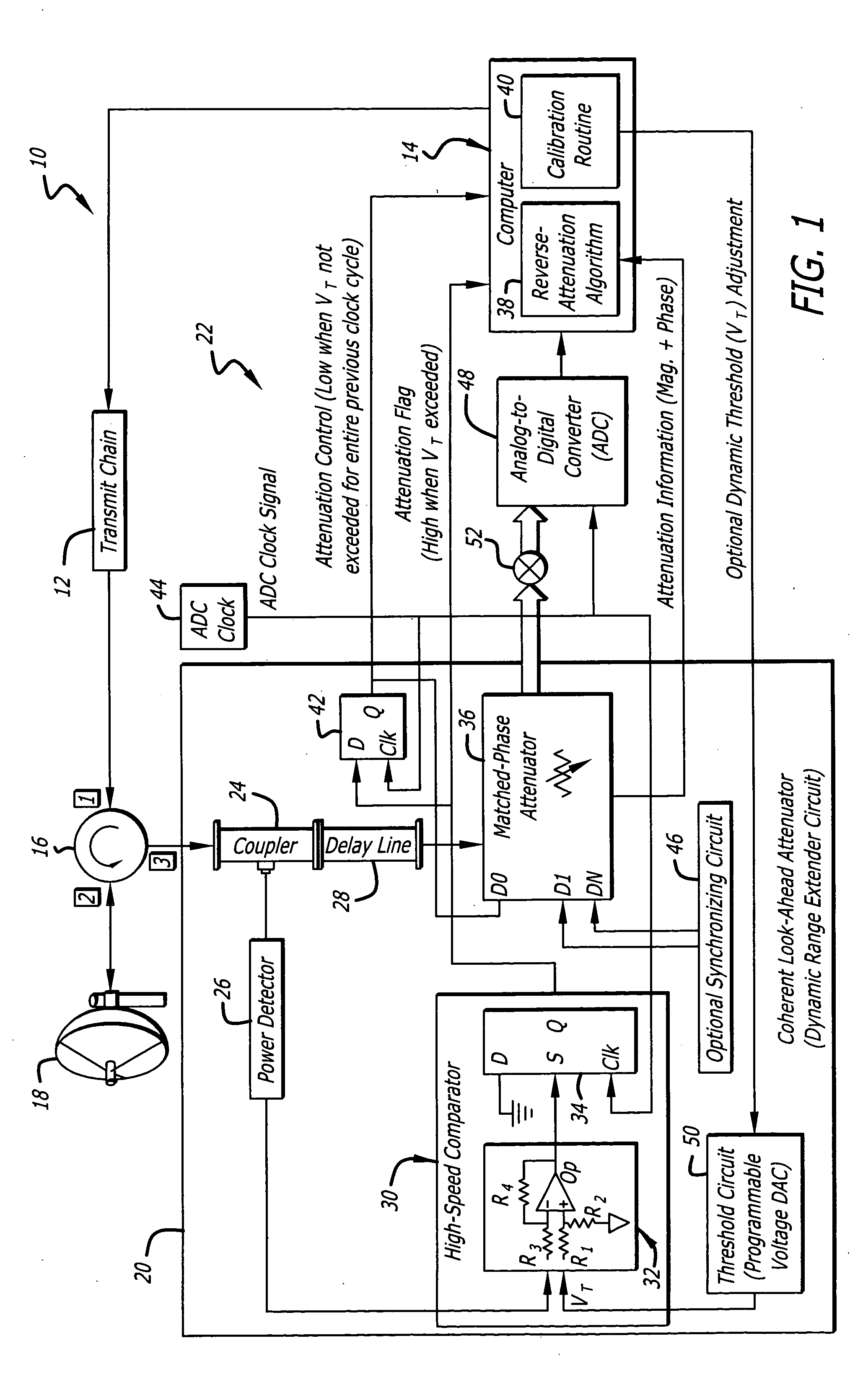
Figure 2 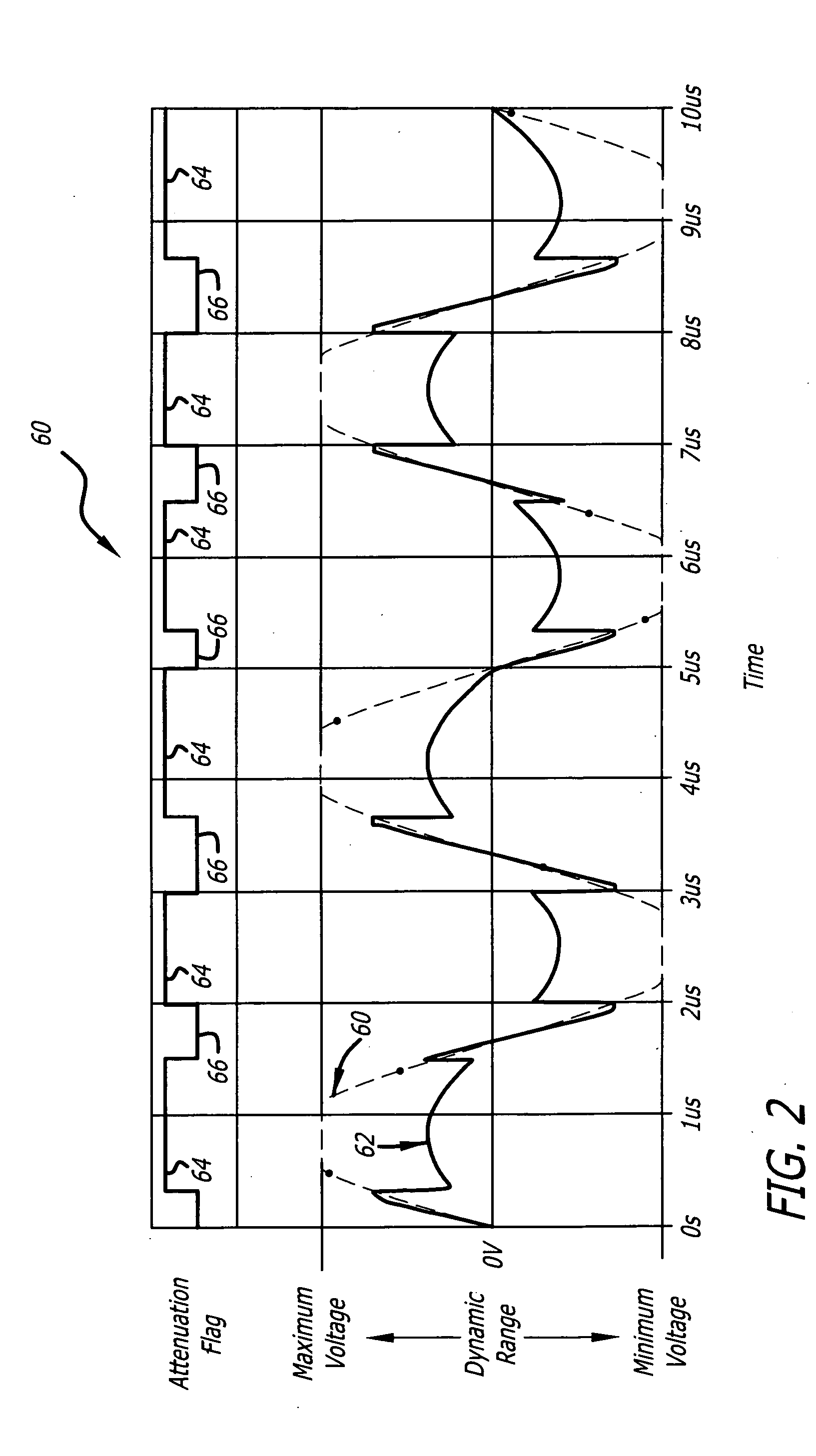
Figure 3
Abstract
Description
BACKGROUND OF THE INVENTION
[0001] 1. Field of Invention
[0002] This invention relates to electrical and electronic circuits and systems. Specifically, the present invention relates to systems and methods for improving the dynamic range of circuits, such as radar and Radio Frequency (RF) communications receivers.
[0003] 2. Description of the Related Art
[0004] Receivers are employed in various demanding applications including radar, ladar, and microwave sensing systems. Such applications demand receivers that can accommodate various signal magnitudes including both faint and intense signals without causing signal distortion, such as spurs, clipping, or intermodulation distortion. This necessitates receivers with high dynamic ranges, preferably above 100 dB. High dynamic range receivers are particularly important in communications systems and projected munition targeting applications, where sufficient system resolution and signal detection capability are required to extract desired s...
Examples
Embodiment Construction
[0018] While the present invention is described herein with reference to illustrative embodiments for particular applications, it should be understood that the invention is not limited thereto. Those having ordinary skill in the art and access to the teachings provided herein will recognize additional modifications, applications, and embodiments within the scope thereof and additional fields in which the present invention would be of significant utility.
[0019]FIG. 1 is a diagram of a transceiver 10 employing an efficient coherent look-ahead attenuator 20 according to an embodiment of the present invention. For clarity, various features, such as power supplies, automatic gain control circuits, computer operating systems, and so on, have been omitted from the figures. However, those skilled in the art with access to the present teachings will know which components and features to implement and how to implement them to meet the needs of a given application.
[0020] In the present speci...