
Angular velocity measuring device and leg-moving robot
a technology of angular velocity and measuring device, which is applied in the direction of electric controllers, instruments, ignition automatic control, etc., can solve the problems of drifting from the actual angular velocity, and achieve the effect of increasing the accuracy of the estimated value of the posture angle and easy accumulation of errors
Patent Information
- Authority / Receiving Office
- US · United States
- Patent Type
- Applications(United States)
- Current Assignee / Owner
- Publication Date
- 2007-07-05
- Estimated Expiration
- Not applicable · inactive patent
Smart Images
Figure 1 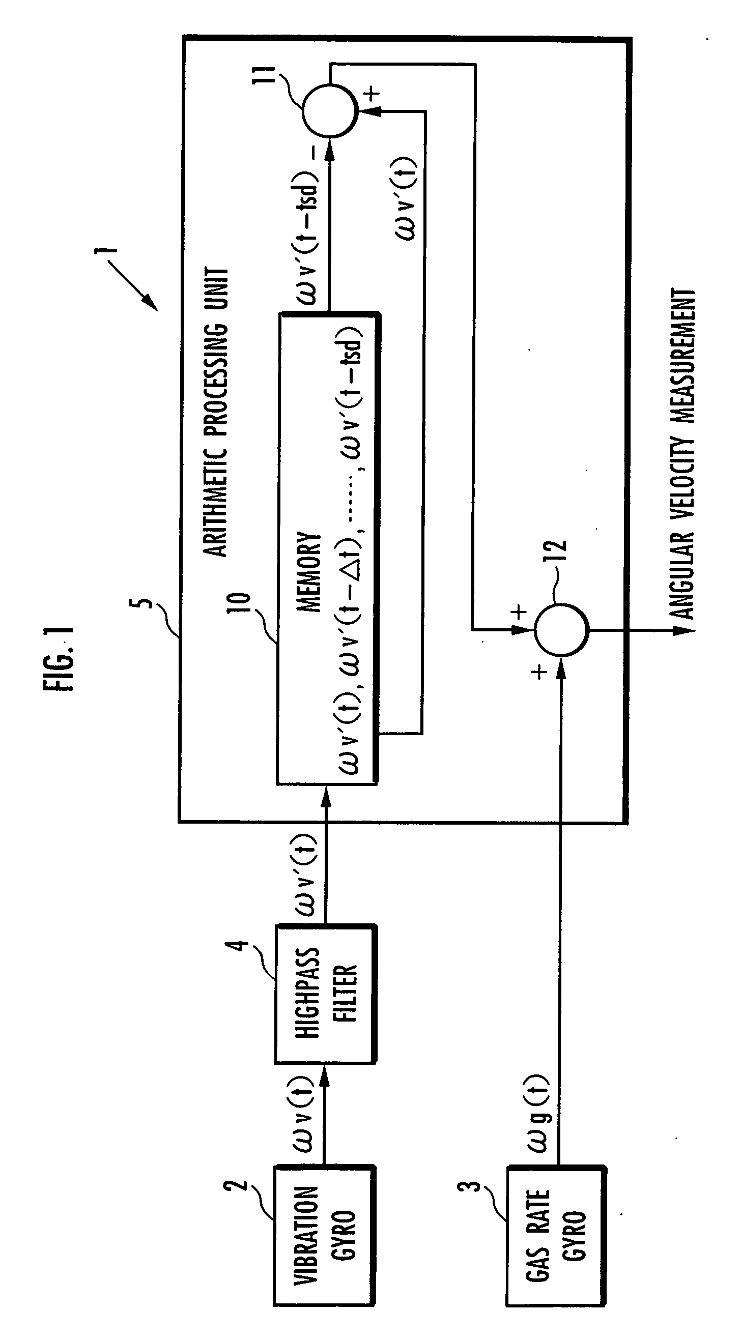
Figure 2 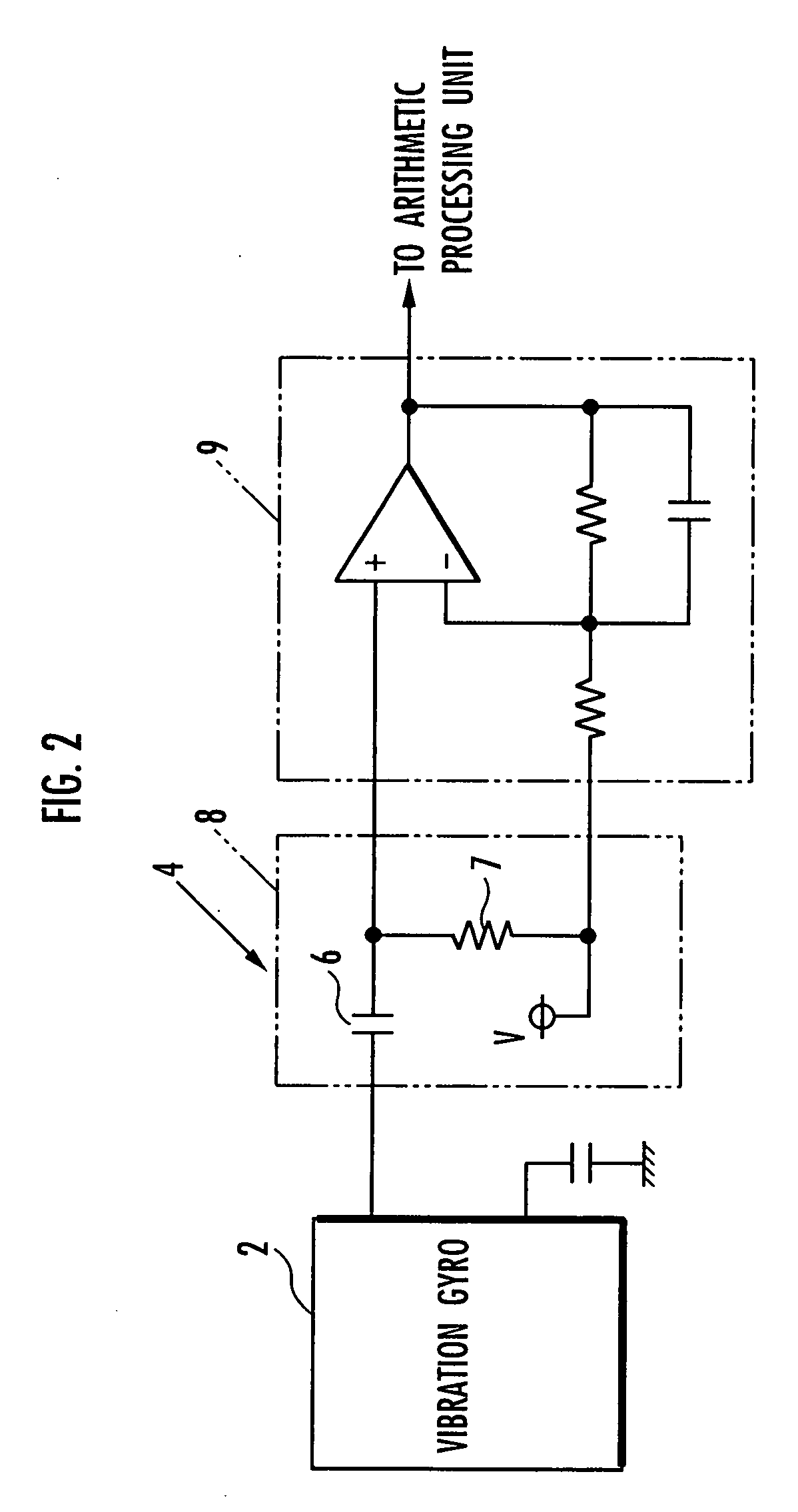
Figure 3
Abstract
Description
FIELD OF THE INVENTION
[0001] The present invention relates to an angular velocity measuring device and a leg-moving robot. BACKGROUND ART
[0002] As sensors (rate gyroscopes) for detecting angular velocities, a vibratory gyroscope, a gas rate gyroscope, and the like are well-known. Moreover, for example, as described in Japanese Laid-Open Patent Publication No. 2000-66722 (hereinafter, referred to as patent document 1), there is a known technology in which a movable body is provided therein with a high-sensitivity gyroscope sensor having a relatively narrow detectable angular velocity range and a low-sensitivity gyroscope sensor having a relatively wide detectable angular velocity range, so as to allow selective switching between the low-sensitivity gyroscope sensor and the high-sensitivity gyroscope sensor according to the magnitude of the angular velocity generated in the movable body, whereby the angular velocity can be measured in a wide range.
[0003] Now, for example, a biped m...
Examples
Embodiment Construction
[0029] An embodiment of an angular velocity measuring device according to the present invention will be described below with reference to FIG. 1 to FIG. 5. FIG. 1 is a block diagram showing a configuration of an angular velocity measuring device according to this embodiment; FIG. 2 is a circuit diagram showing a concrete circuit configuration between a vibratory gyroscope 2 and an arithmetic processing unit 5 shown in FIG. 1; FIG. 3 is a graph showing an output characteristic of the vibratory gyroscope; FIG. 4 is a graph showing an output characteristic of a gas rate gyroscope; and FIG. 5 is a graph showing an output characteristic of the angular velocity measuring device shown in FIG. 1.
[0030] Referring to FIG. 1, an angular velocity measuring device 1 of this embodiment includes a vibratory gyroscope 2 as a first sensor, a gas rate gyroscope 3 as a second sensor, a highpass filter 4 (high-frequency pass filter) that receives a detected output ωv of the vibratory gyroscope 2, and ...