
Hybrid frequency contactless transponder unit, module for and method of manufacturing
a technology of contactless transponder and module, which is applied in the field of contactless transponder module, contactless transponder module, etc., can solve the problems of not being able to operate in several frequencies at the same time, not being able to show the structure of such transponders in documents, and never reaching mass production volume of products. , to achieve the effect of improving the known manufacturing techniques of hybrid frequency contactless transponder units
Patent Information
- Authority / Receiving Office
- US · United States
- Patent Type
- Applications(United States)
- Current Assignee / Owner
- Publication Date
- 2007-08-23
- Estimated Expiration
- Not applicable · inactive patent
Smart Images
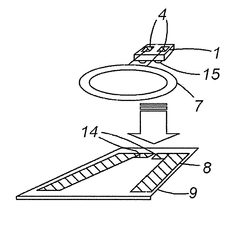
Figure 1 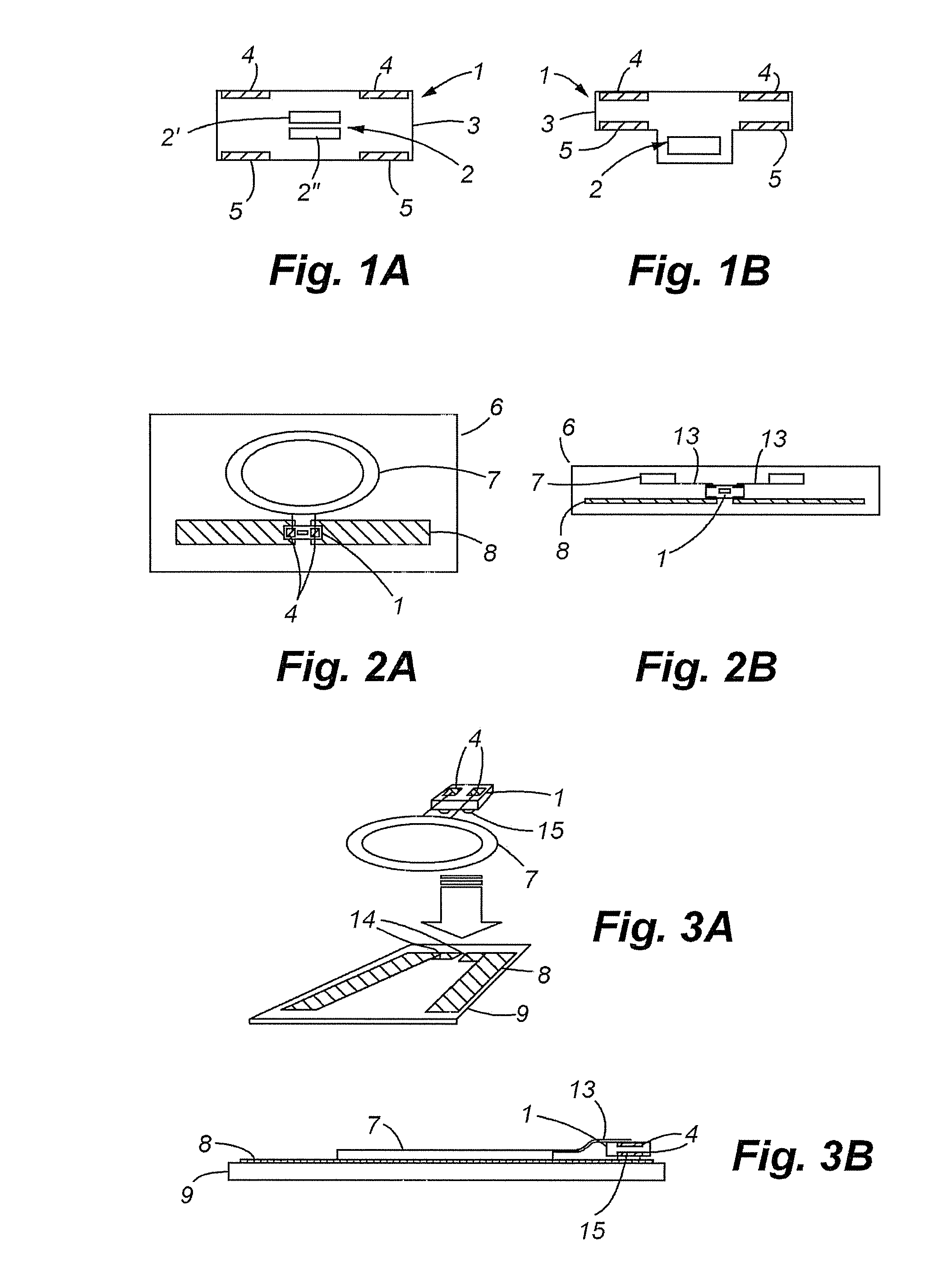
Figure 2 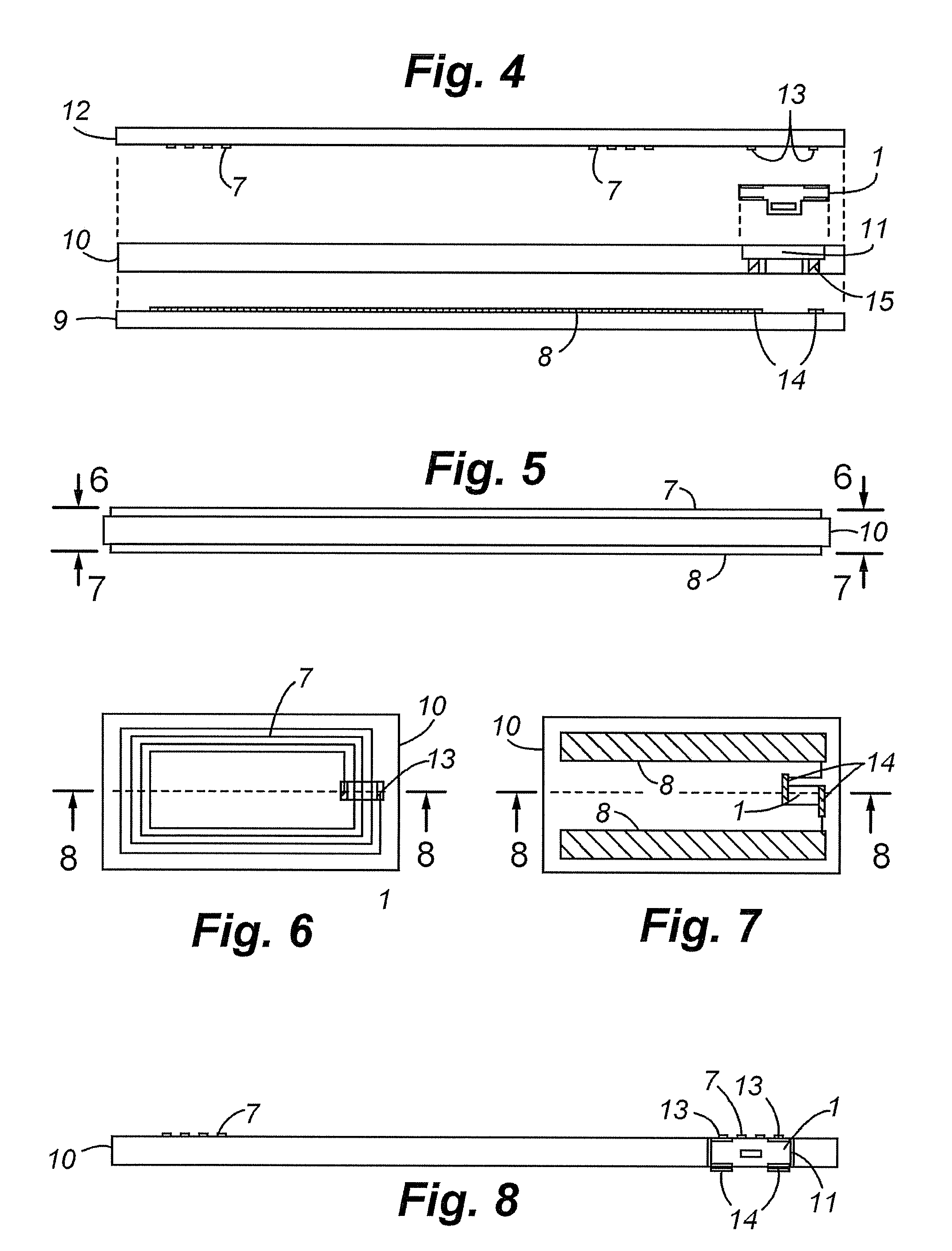
Figure 3
Abstract
Description
FIELD OF THE INVENTION
[0001] The invention relates to a module for a contactless transponder unit, a contactless transponder unit with such a module and methods of manufacturing such contactless transponder unit. In particular, the invention concerns hybrid frequency contactless transponder units. As used herein, “hybrid” is understood to refer to contactless transponder units having two different antennas operating in two different frequency ranges. Contactless smart cards are one of the particular embodiments of the invention. STATE OF THE ART
[0002] The different transmission frequencies of transponders are classified into three basic ranges:
[0003] Low Frequency (LF): 30-300 kHz
[0004] High Frequency (HF): 3-30 MHz (also called Radio Frequency (RF))
[0005] Ultra High Frequency (UHF): 300 MHz-3 GHz (also including Microwave (>3 GHz))
[0006] LF and HF antennas are typically loop antennas (made of wire or band), whereas UHF antennas have more varied forms (dipole, patch, slot a...
Examples
Embodiment Construction
[0034] In FIGS. 1A and 1B, two different embodiments of a chip module 1 of the invention are represented. As with all transponder chip modules, they contain at least a transponder chip 2 or two transponder chips 2′ and 2″ embedded in an insulating housing 3, the chip module being connected (not shown) to external conductive contact zones 4 and 5 at the surface of the housing. There are, in fact, two pairs 4 and 5 of contact zones, each positioned on one of the upper and lower surface of the chip module 1. The housing 3 can have many shapes, for example a square with two well defined upper and lower surface as in FIG. 1A, or also T-shaped as in FIG. 1B, in which the lower surface shows different levels. The contact zones 4 and 5 can be placed anywhere on these surfaces, such that each pair is placed on an opposite side of the chip module 1. A symmetrical position of the contact zones as in FIGS. 1A and 1B may be beneficial, but is not required. The internal structures of the chip mod...