
Electromagnetic apparatus and method for controlling fluid flow
a technology of electromagnetic apparatus and fluid flow, applied in the direction of diaphragm valve, valve details, valve arrangement, etc., can solve the problems of metal problems, reduce the longevity of batteries, and damage to armatures, so as to reduce energy consumption, reduce energy waste, and reduce energy consumption. effect of large amoun
Patent Information
- Authority / Receiving Office
- US · United States
- Patent Type
- Applications(United States)
- Current Assignee / Owner
- Publication Date
- 2007-10-18
- Estimated Expiration
- Not applicable · inactive patent
Smart Images
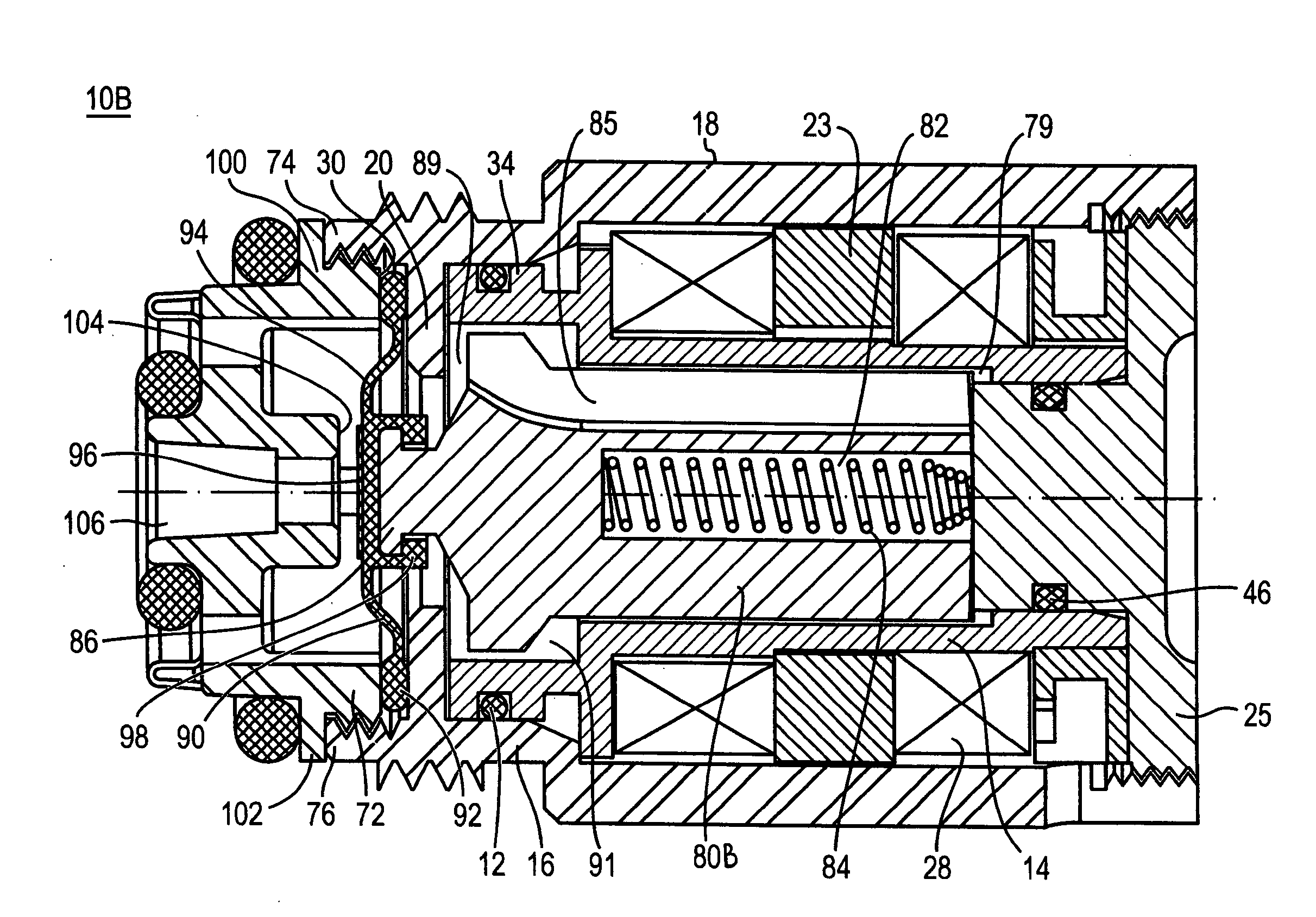
Figure 1 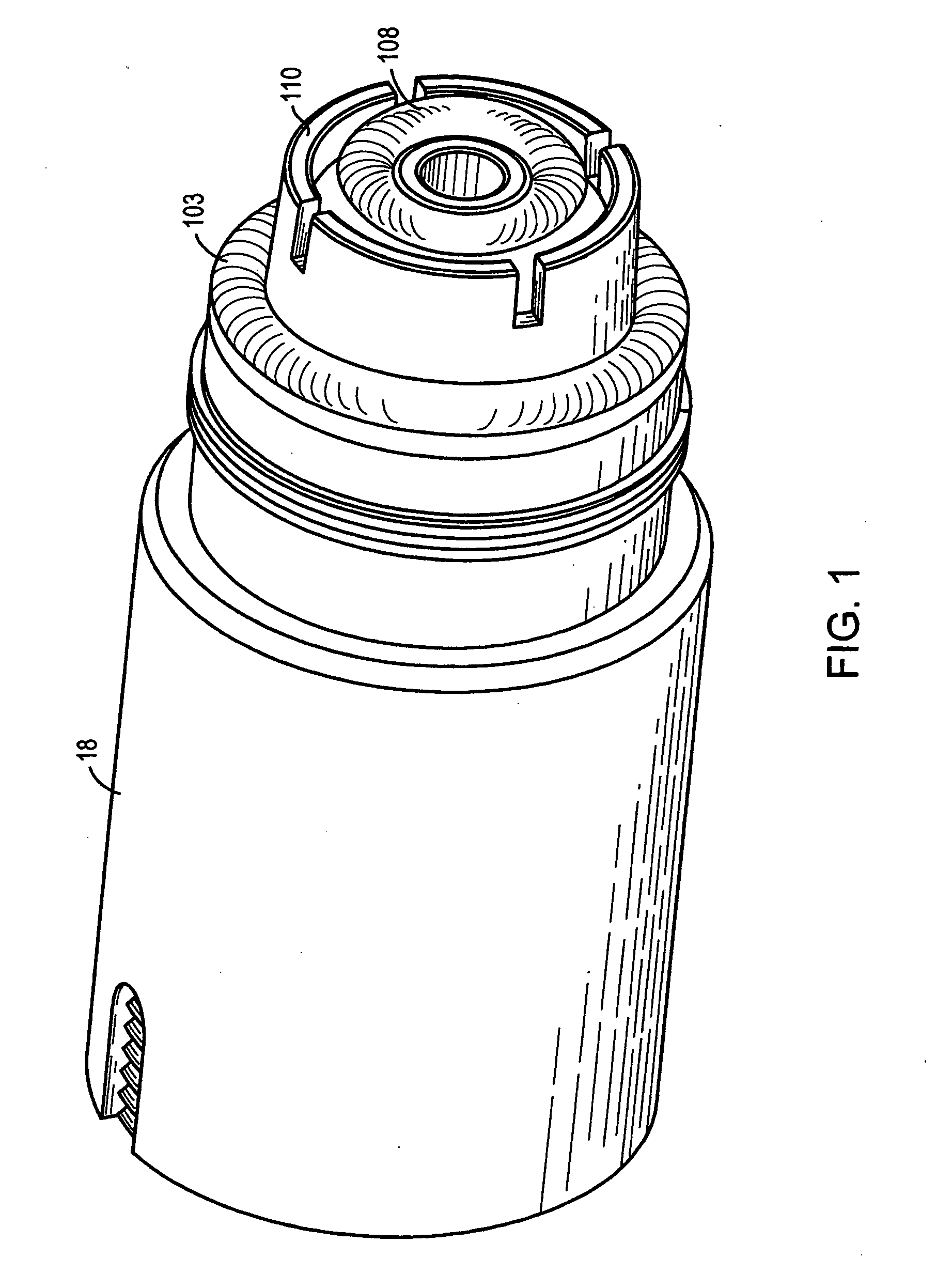
Figure 2 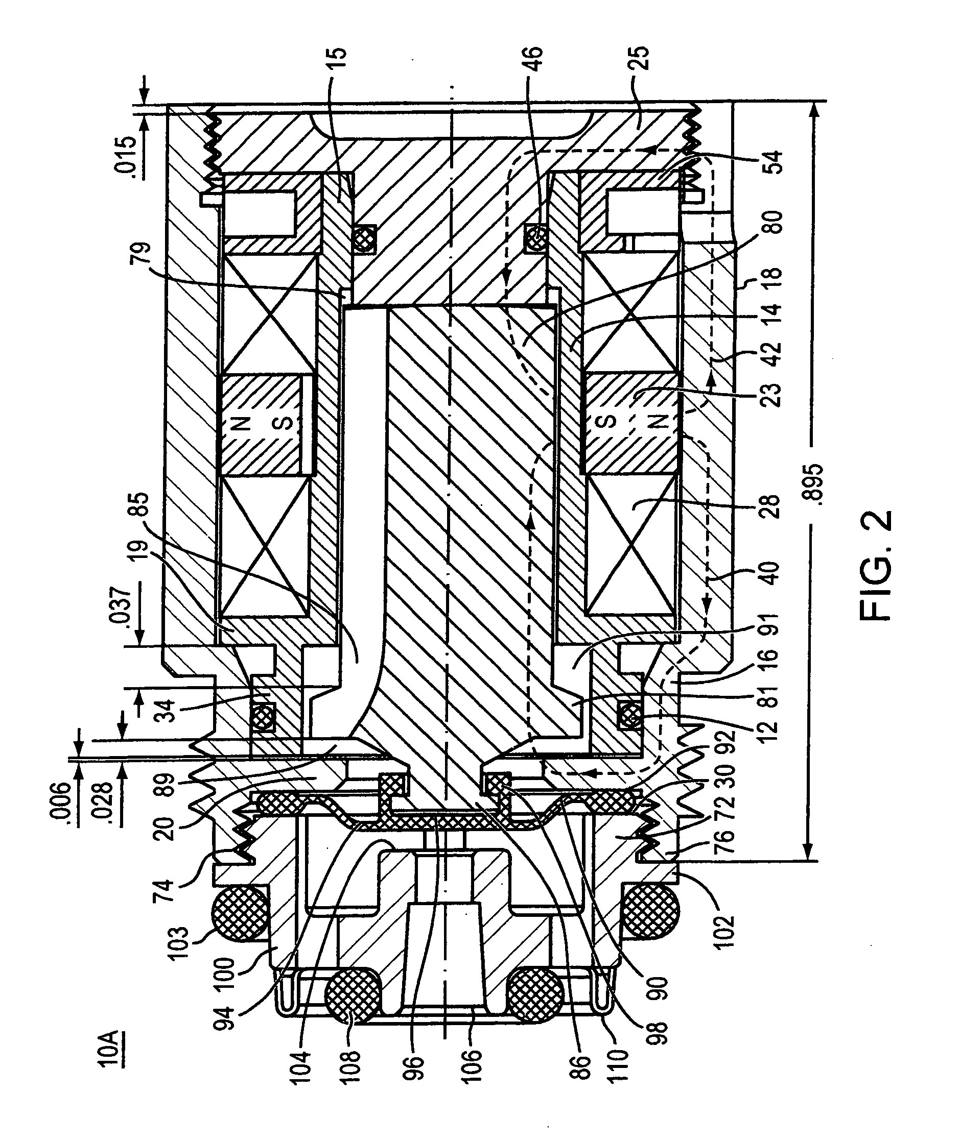
Figure 3
Abstract
Description
[0001] This application also claims priority from U.S. provisional Application 60 / 659,343 filed on Mar. 5, 2005. This application is also a continuation-in-part of U.S. application Ser. No. 10 / 421,359, filed on Apr. 23, 2003, entitled “Apparatus and Method for Controlling Fluid Flow,” which is a continuation of PCT Application PCT / US01 / 51098, filed on Oct. 25, 2001, which is continuation-in-part of U.S. application Ser. No. 09 / 696,154, filed on Oct. 25, 2000, now U.S. Pat. No. 6,609,698. This application is also a continuation-in-part of U.S. application Ser. No. 10 / 610,954, filed on Jul. 1, 2003, which is a continuation of U.S. application Ser. No. 10 / 037,473, filed on Oct. 19, 2001, which is a continuation of U.S. application Ser. No. 09 / 514,491, filed on Feb. 29, 2000, now U.S. Pat. No. 6,305,662, is a continuation-in-part of U.S. application Ser. No. 09 / 924,130, filed on Aug. 7, 2001, now U.S. Pat. No. 6,450,478. The disclosure of all of the above-mentioned applications is consi...
Examples
Embodiment Construction
[0034] Industrial, agricultural and household systems use various types of valves that use electromagnetic actuators for controlling fluid flow. Referring to FIG. 1, an electrically operable valve 10A uses force from magnetic fields and the biasing force of a radial magnet to drive an armature within an actuator into a valve seat, thereby stopping flow through a conduit, and to move the armature away from the valve seat, thereby opening the valve once more.
[0035]FIGS. 1 and 2 illustrate an embodiment of the electrically operable valve 10A. As seen in FIG. 2, the valve actuator 10A includes an annular magnet 23, a rear pole piece 25, a ferromagnetic armature 80, and the solenoid windings 28 wound about a solenoid bobbin 14. The valve also includes a resilient membrane 90 and a replaceable pilot body member 100, which defines the valve geometry. Resilient membrane 90 includes a thickened peripheral rim 92, flexible portion 94, portion 98, surrounding the plunger tip, and deformable s...