
Arc-cutting guide for a portable powered hand tool
a portable, hand tool technology, applied in the direction of manufacturing tools, metal-working machine components, metal working apparatuses, etc., can solve the problems of increasing the cost of clamping, obstructing the path traced by the user's hand and lower arm, and the knob adjacent to the handle is difficult to use, so as to achieve convenient and accurate measurement. , the effect of effective and efficient operation
Patent Information
- Authority / Receiving Office
- US · United States
- Patent Type
- Applications(United States)
- Current Assignee / Owner
- Publication Date
- 2009-02-12
- Estimated Expiration
- Not applicable · inactive patent
Smart Images
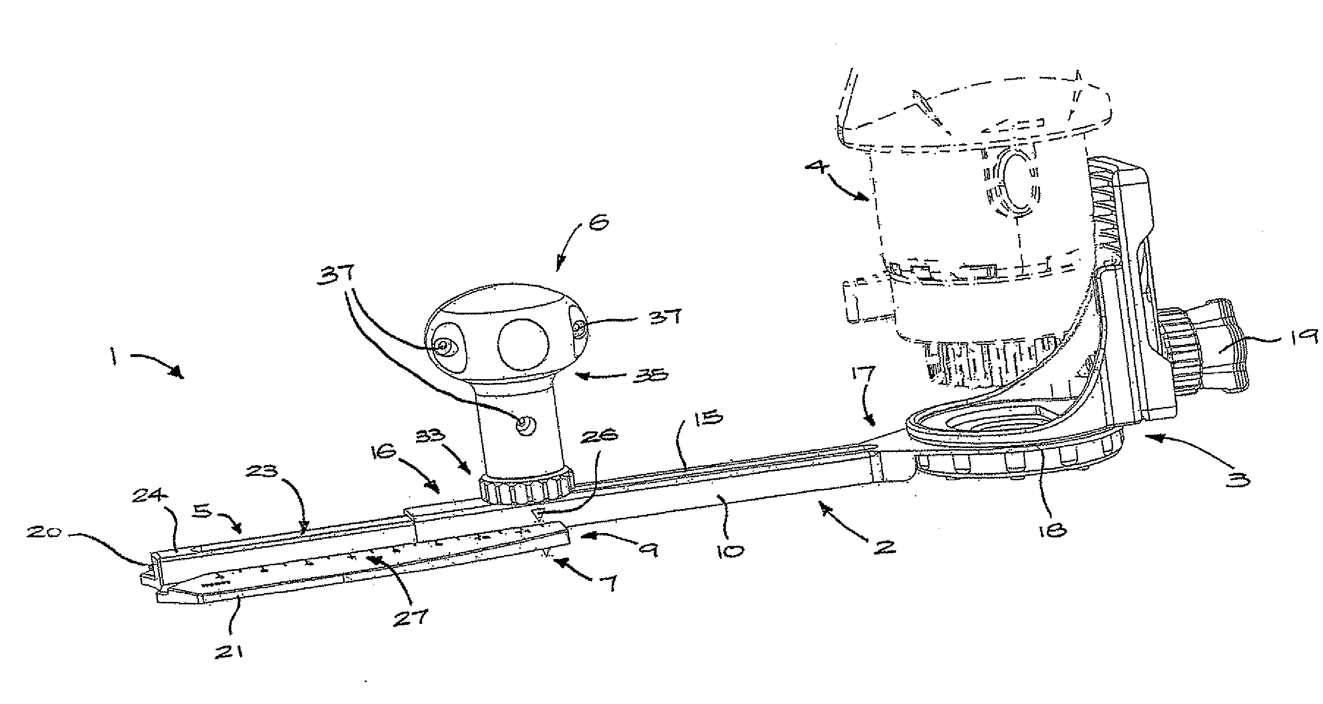
Figure 1 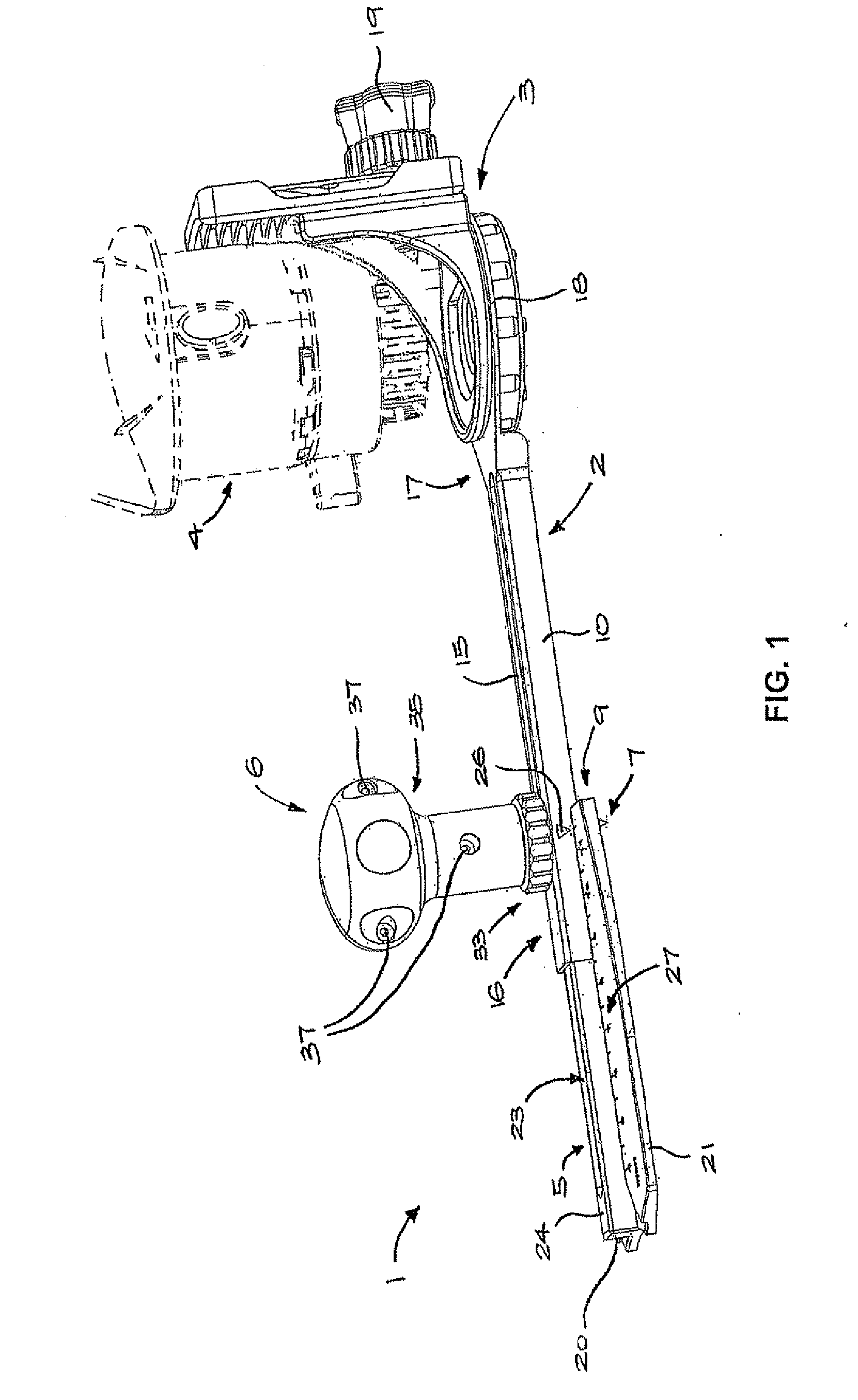
Figure 2 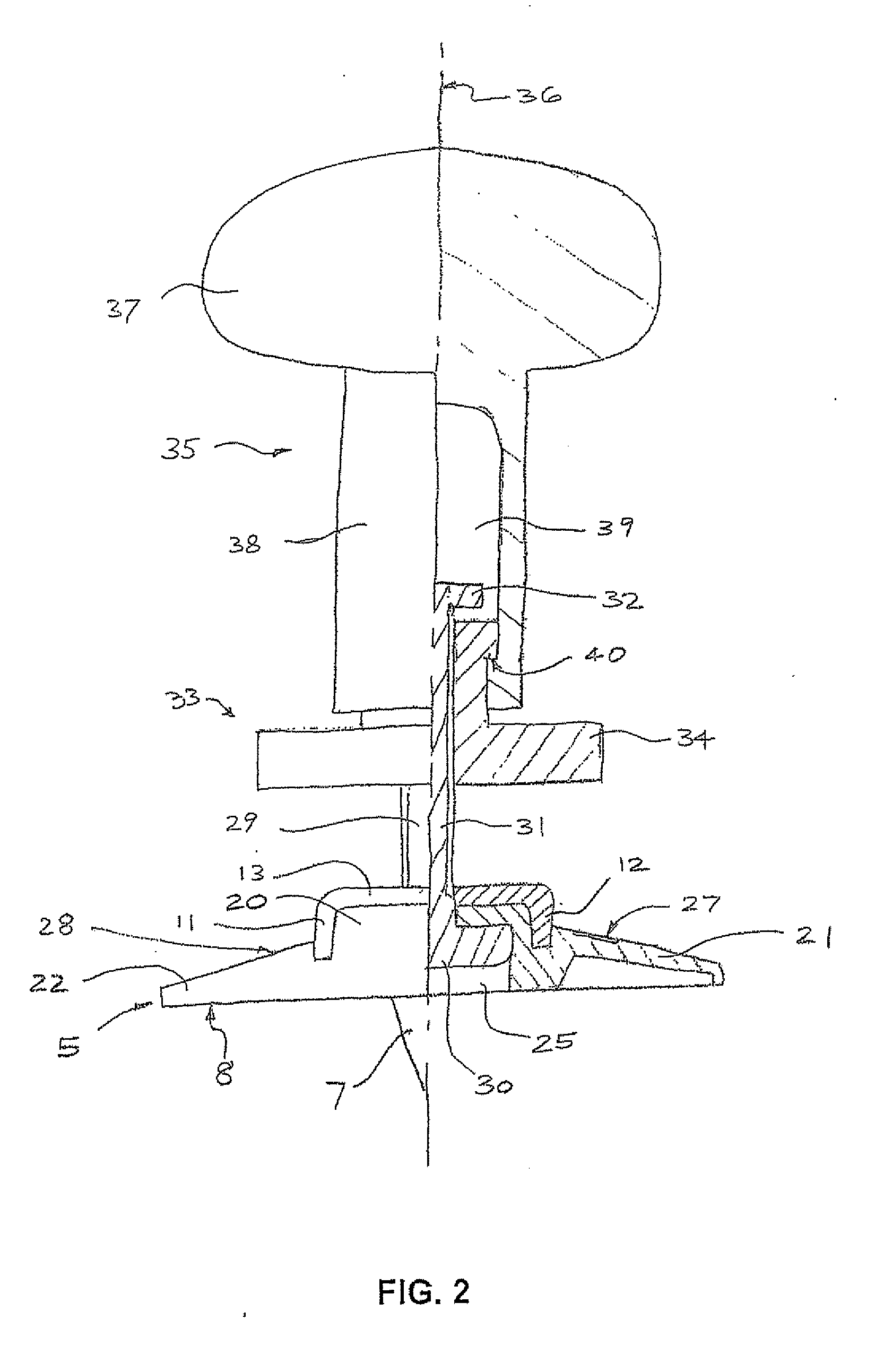
Figure 3
Abstract
Description
TECHNICAL FIELD
[0001] The present invention relates to an arc-cutting guide for forming circular and arcuate cuts in a workpiece with a powered hand tool, such as a rotary cutting tool.BACKGROUND OF THE INVENTION
[0002] Craftsmen, as well as hobbyists, commonly have a need to cut out large circular or arcuate pieces of wood, carpet and tile, or the like, to make many different products. Numerous arc-cutting guides have been used for guiding cutters for such work. Most of these devices consist of a swing arm with a cutting tool holder of some kind, a point or means for defining a pivot, and possibly a measuring device. By attaching a rotary cutter to a swing arm of known length which is then anchored at a pivot point on a workpiece, the cutter can be moved along a circumferential path to shape the workpiece to the desired radius.
[0003] U.S. Pat. No. 6,752,572 describes an arc-cutting guide comprising a swing arm defining a longitudinally extending channel and a slot. A fixture at one end...
Examples
Embodiment Construction
[0029]Referring to the drawings, particularly FIGS. 1 and 2, an arc-cutting guide 1 includes an elongate a swing arm 2 with a fixture 3 at one end for mounting a hand tool, such as the rotary electric cutting tool 4 (shown in dashed outline in FIG. 1). A slider member 5 is telescopically engaged with the swing arm 2 and connected thereto by the handle assembly 6. A point 7 projects from a planar lower face 8 of the slider member 5. The point 7 is offset longitudinally as far as possible from a centre of the slider member, being positioned adjacent to a first end 9 of the slider member 5.
[0030]The swing arm 2 includes a bar portion 10 having a U-shaped section comprising parallel flanges 11, 12 joined by a web 13 to define an inverted channel 14. A longitudinal slot 15 is formed centrally in the web 13, extending from first to a second end 16, 17 of the bar portion 10. At the second end 17 a ring portion 18 is formed integrally with the bar portion 10. The fixture 3 is mounted on the...