
Heat exchanger
a heat exchanger and heat exchanger technology, applied in the direction of heat exchangers, stationary tubular conduit assemblies, other heat production devices, etc., can solve the problems of loss of efficiency in this design, inability to perform both heating and cooling duties at maximum efficiency, and inability to achieve optimal performance efficiency, good and unique combination, and loss of efficiency
Patent Information
- Authority / Receiving Office
- US · United States
- Current Assignee / Owner
- Publication Date
- 2009-04-30
- Estimated Expiration
- Not applicable · inactive patent
Smart Images
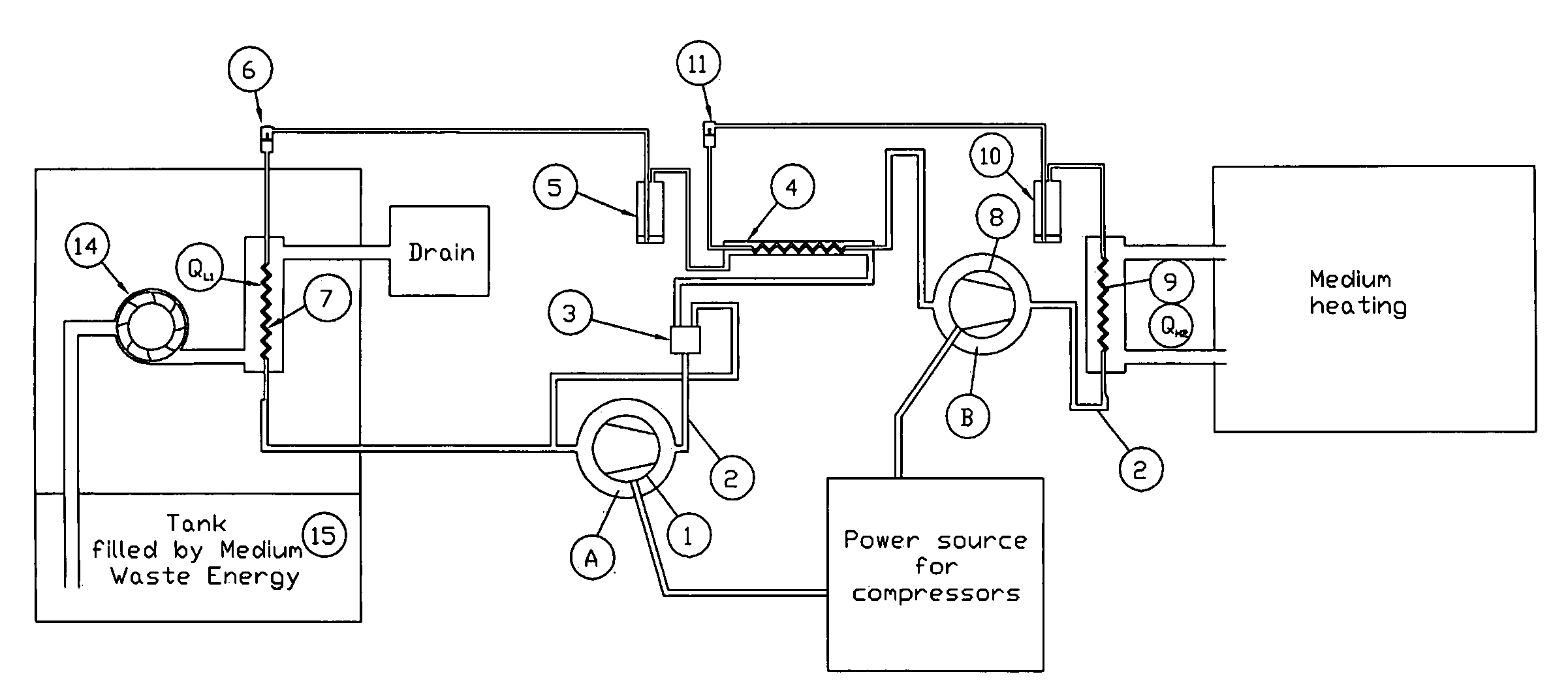
Figure 1 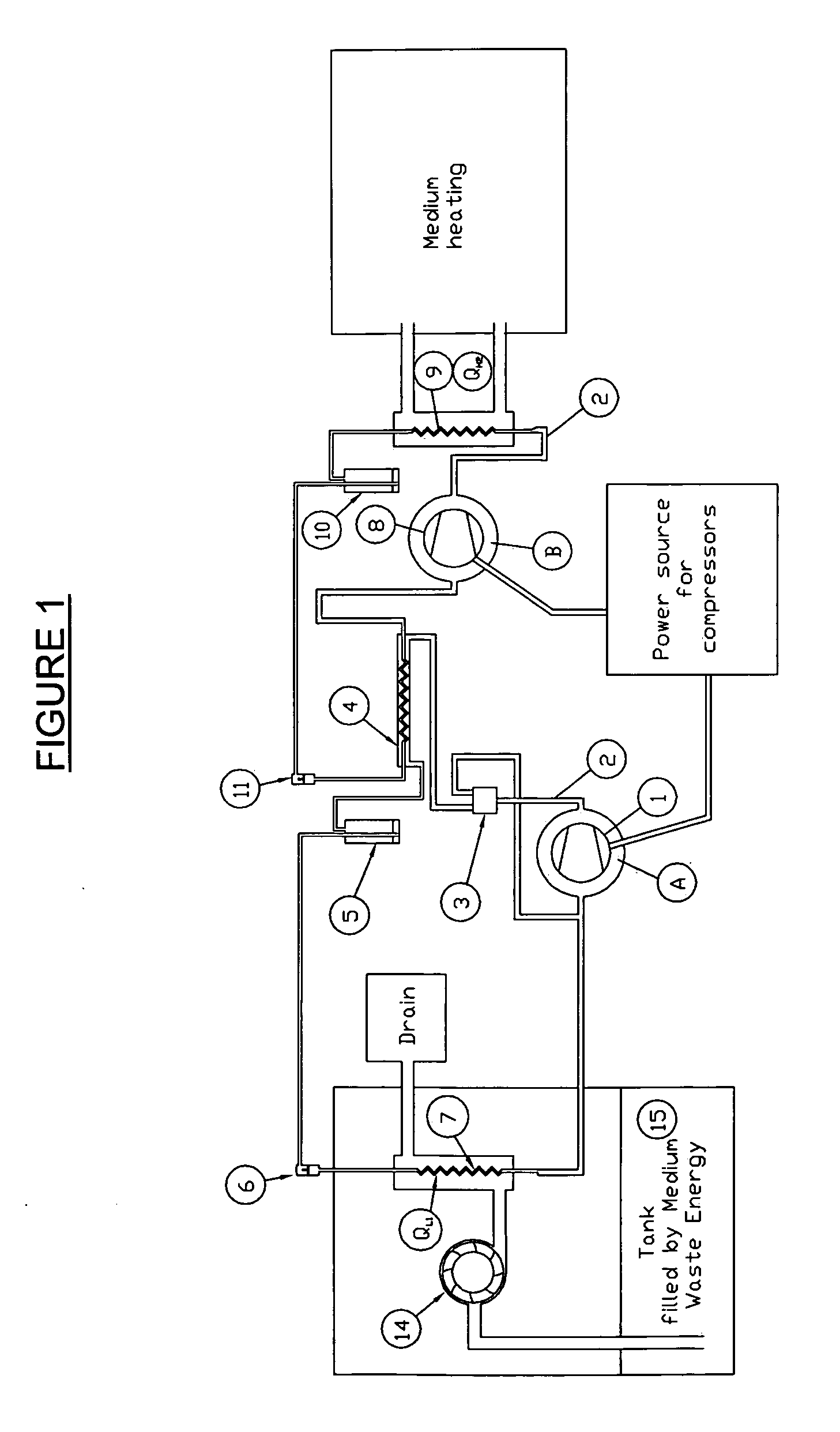
Figure 2 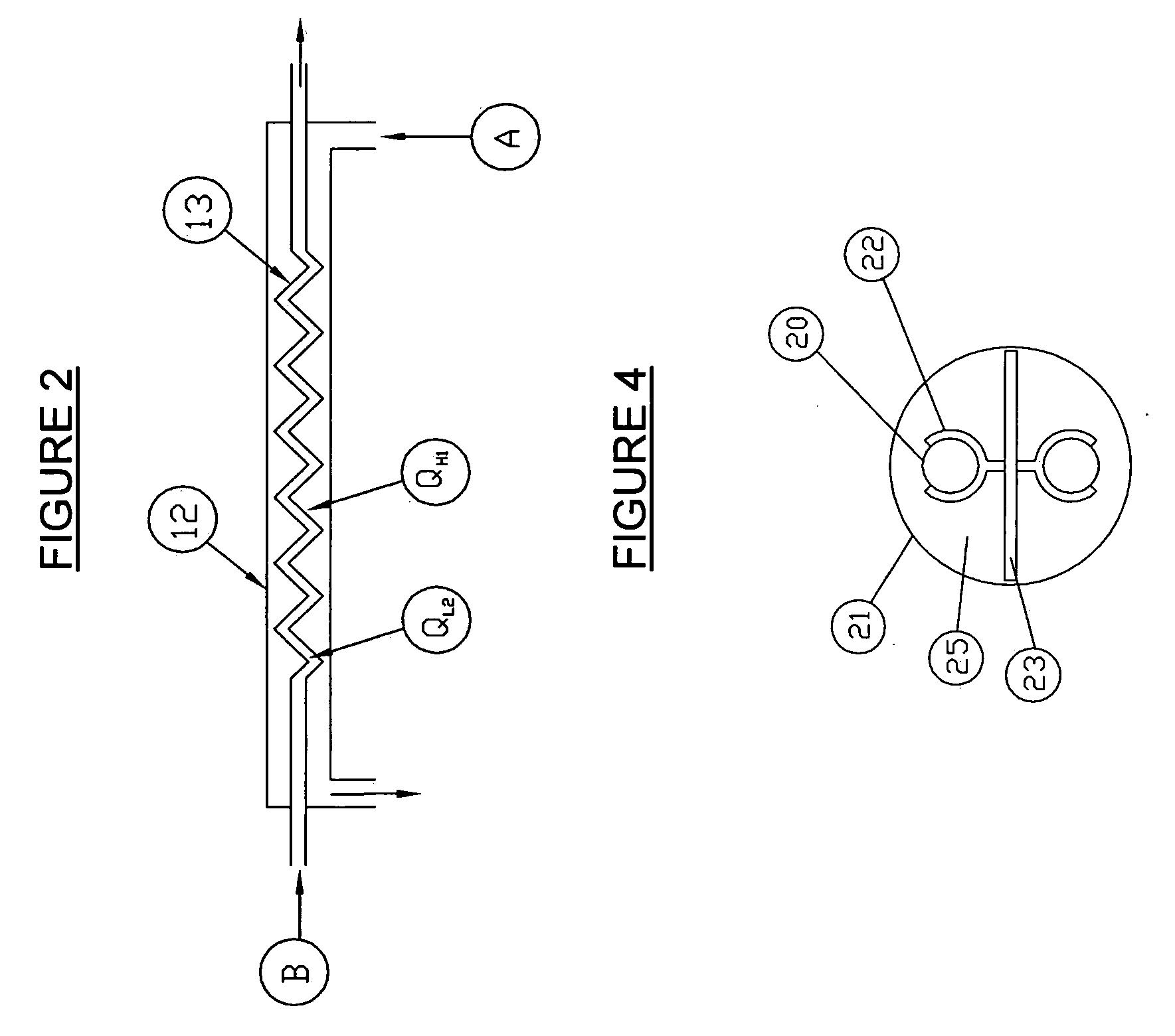
Figure 3
Abstract
Description
[0001] This application is based on the Provisional Patent application US61 / 001,063, filed on Oct. 21, 2007.
[0002] The present invention relates to a method and apparatus for a heat exchange system. There are known systems using refrigerants, heat exchange coils, and geothermal applications for extracting heat from the ground or warm waste water as well as staging a heat increase incrementally.
[0003] The present invention comprises a system based on optimum work ranges for various known refrigerants that can be adapted for diverse environments.BACKGROUND
[0004] There is known U.S. Pat. No. 4,149,585 relating to a method for transferring heat between fluids with geothermal application. This invention uses the principle of a cascading heat transfer using the same refrigerant from compressor to compressor thus increasing its temperature. This is an efficient but very costly system.
[0005] There is also known U.S. Pat. No. 4,413,669 for a method of heat extraction from water through a expansio...
Examples
Embodiment Construction
[0042]The present invention optimizes known prior art systems into a cascade of heat exchange. There are two closed loops (see FIGS. 1 and 3) that can be integrated together to yield optimal results. Referring now to FIGS. 1 and 2:
[0043]First loop comprises a copper piping system 2 filled with refrigerant A. The refrigerant A, in vapor form, is compressed by a scroll or screw compressor 1 thus turning into a liquid in the outer cylinder 12 of a transfer unit 4. Outer cylinder 12 has inlet and outlet to facilitate circulation of refrigerant A within the first loop. Refrigerant A has a condenser capacity QH1 and is provided to transfer latent heat to the refrigerant B to an inner coil 13 placed within said transfer unit 4 in coaxial manner. Inner coil 13 is provided with an inlet and outlet to facilitate circulation of refrigerant B within the second loop. Refrigerant B has an evaporator capacity QL2. A by-pass valve 3 is located between the outer cylinder 12 of transfer unit 4 and th...