
Vehicle failure analysis system, vehicle failure analysis apparatus, and vehicle failure analysis method
Patent Information
- Authority / Receiving Office
- US · United States
- Current Assignee / Owner
- Publication Date
- 2009-11-26
Smart Images
Figure 1 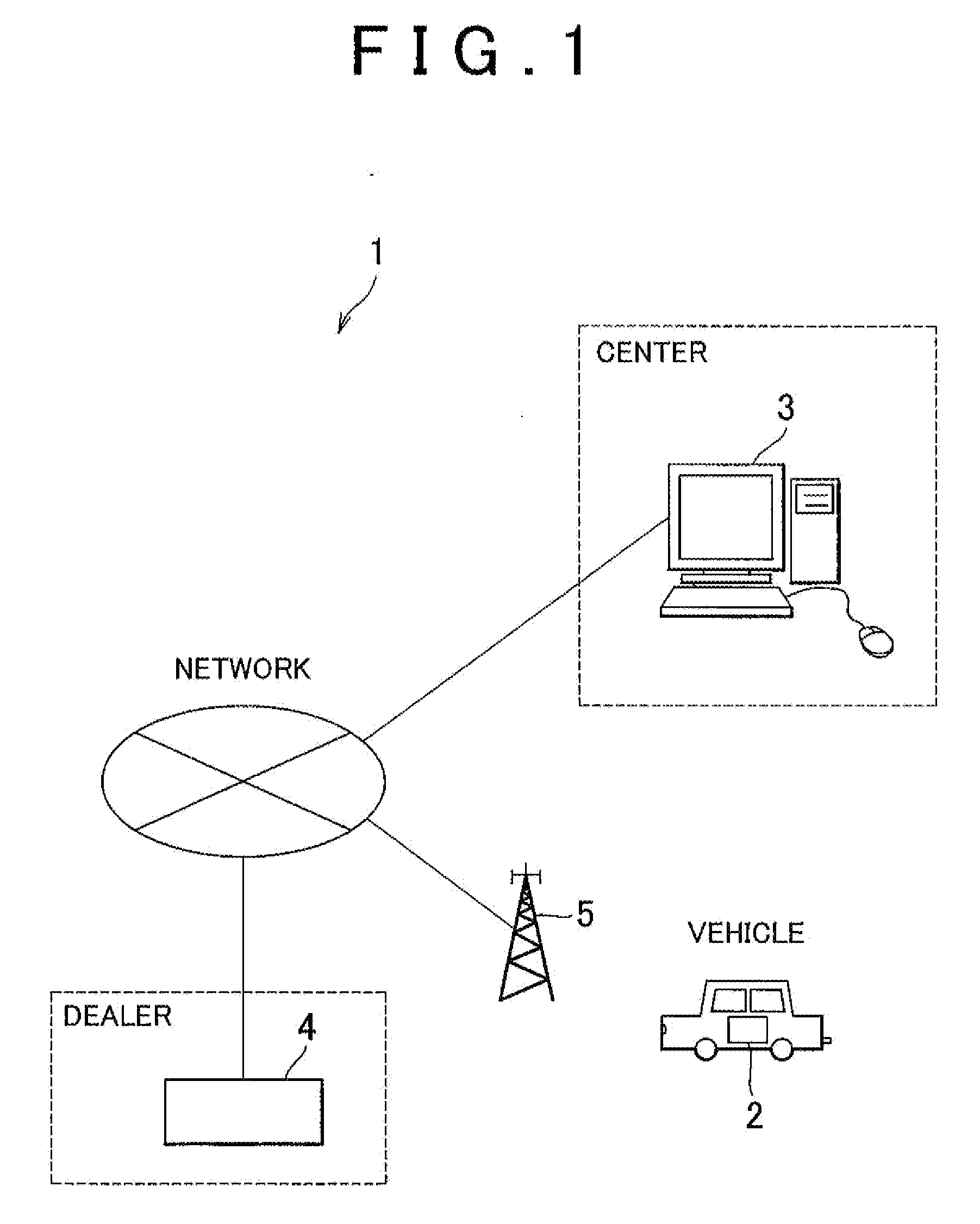
Figure 2 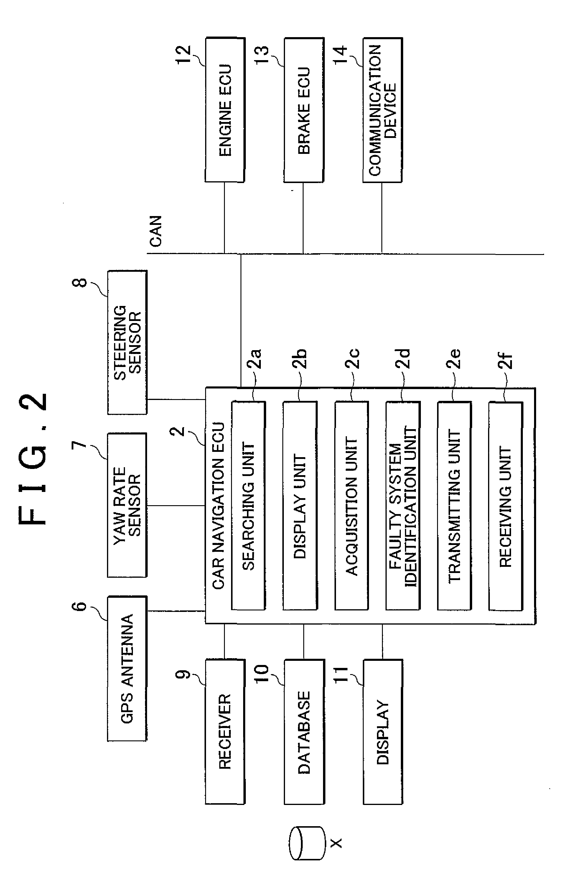
Figure 3
Abstract
Description
INCORPORATION BY REFERENCE
[0001] The disclosure of Japanese Patent Application No. 2008-132303 filed on May 20, 2008, including the specification, drawings and abstract is incorporated herein by reference in its entirety.BACKGROUND OF THE INVENTION
[0002] 1. Field of the Invention
[0003] The invention relates to a vehicle failure analysis system, vehicle failure analysis apparatus and vehicle failure analysis method that are suitably applied to a vehicle, such as a passenger car, a truck and a bus.
[0004] 2. Description of the Related Art
[0005] In recent vehicles, in order to implement various controls in a vehicle, one or more components that are in-vehicle devices or that constitute in-vehicle devices, sensors that detect various pieces of control information related to these components, and an electronic control unit ECU) that controls these components using these various pieces of control information form a group. A group of these components are connected directly or through communicati...
Examples
Embodiment Construction
[0045]FIG. 1 is a block diagram that shows a vehicle failure analysis system according to a first embodiment of the invention. FIG. 2 is a block diagram that shows the configuration of the vehicle failure analysis system at a vehicle side according to the first embodiment of the invention. FIG. 3 is a block diagram that shows the configuration of the vehicle failure analysis system at a road side according to the first embodiment of the invention.
[0046]As shown in FIG. 1, the vehicle failure analysis system 1 according to the first embodiment of the invention includes a car navigation electronic control unit (ECU) 2, a server 3, a diagnostic tool 4 and a base station 5. The car navigation ECU 2 constitutes a plurality of in-vehicle devices mounted on a vehicle. The server 3 is provided at a center at a location other than the vehicle (hereinafter, also referred to as “at a road side” in this specification). The diagnostic tool 4 is provided at a dealer at a road side. The server 3, ...