

High Frequency Module for Filling Level Measurements in the W-Band
Patent Information
- Authority / Receiving Office
- US · United States
- Current Assignee / Owner
- Publication Date
- 2010-04-29
Smart Images
Figure 1 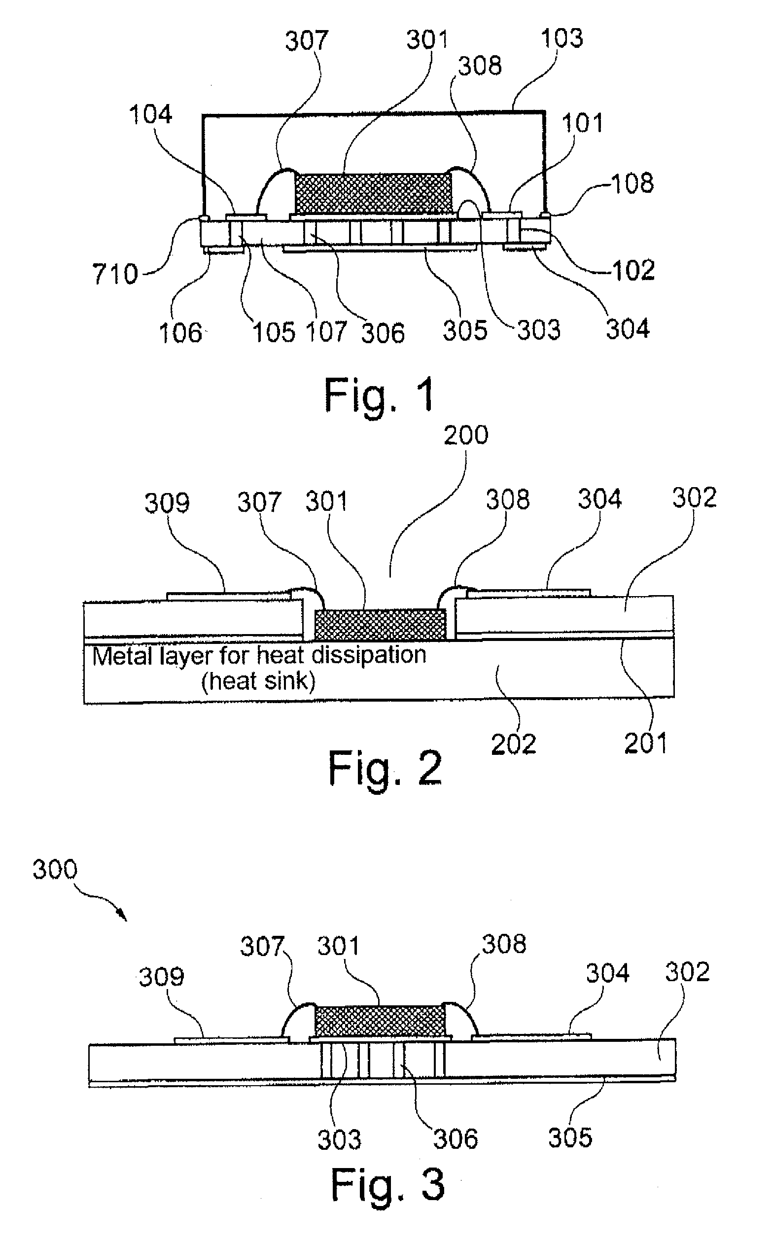
Figure 2 
Figure 3
Abstract
Description
REFERENCE TO RELATED APPLICATIONS
[0001] This application claims the benefit of the filing date of EP Application Serial No. 08 167 856.7 filed on Oct. 29, 2008 and U.S. Provisional Patent Application Ser. No. 61 / 109,319 filed on Oct. 29, 2008, the disclosure of which applications is hereby incorporated herein by reference.FIELD OF THE INVENTION
[0002] The present invention relates to fill level measuring. In particular, the invention relates to a high-frequency module for fill level measuring at frequencies of more than 75 GHz, to a fill level radar with a high-frequency module, and to a method for operating a fill level sensor with a high-frequency module.TECHNOLOGICAL BACKGROUND
[0003] The use of high frequencies in fill level measuring provides many advantages. For example, in this way the components of sensors may be kept smaller.
[0004] In fill level measuring in the high-frequency range there are three different frequency bands. Firstly the so-called C-band, which ranges from 4 to 8 ...
Examples
Embodiment Construction
[0042]The illustrations in the figures are diagrammatic and not to scale.
DETAILED DESCRIPTION
[0043]In the following description of the figures the same reference characters are used for identical or similar elements.
[0044]FIG. 1 shows a cross-sectional view of a high-frequency module that comprises a microwave semiconductor (chip) 301 which has been placed on a base board 107 (for example made of ceramic material). Between the base board 107 and the chip 301 there is a metal layer 303.
[0045]The chip 301 is connected to the ongoing signal lines 104 or 101 by way of the bond wires 307, 308. By way of corresponding through-hole platings 102, 105 the signal lines 101, 104 are led through the base board 107 and then continue on the underside of the base board (see reference characters 304, 106).
[0046]Furthermore, through-hole platings 306 are provided underneath the chip 301, which through-hole platings 306 are connected to the metallic mass connection 305 on the underside of the base bo...